Part Number: PSPICE-FOR-TI
Other Parts Discussed in Thread: LMG5200
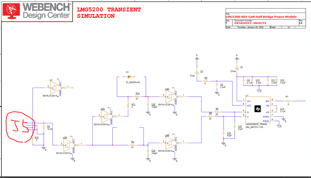
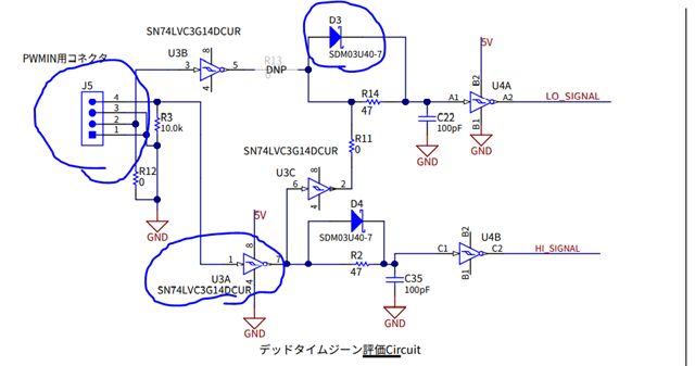
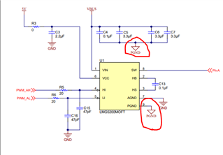
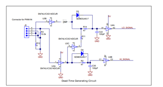
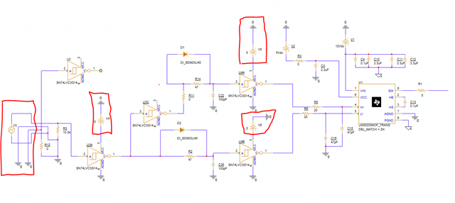
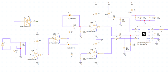
Please help someone. This is about the simulation of the LMG5200. The first image above is the circuit created by the LMG5200, and the second is the Hi and Lo inverting circuits I want to create. I'm done halfway, but the problem is with the connection of J5 in this second image.

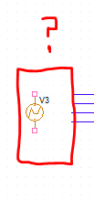
I want to use the PWM source attached to this J5 connection. Could you tell me how to connect or connect diagram if I inserted it? Also, for PWM sources, you can follow the same connection as the J5 connector. The "top" of the PWM source corresponds to pin 4 of the J5 connector. The "bottom" of the PWM source corresponds to pin 1 of the J5 connector (ground). I've been told a little bit before, but I asked for help here because I don't know exactly how to connect. I have no date. So I want someone to cooperate. I will give you something, so thank you very much.
Tosi.