This thread has been locked.

If you have a related question, please click the "Ask a related question" button in the top right corner. The newly created question will be automatically linked to this question.

TIDA-00827: Software for Trapezoidal control

Part Number: TIDA-00827
Other Parts Discussed in Thread: TIDA-01362, TIDA-00274, TIDA-010056, DRV8313, DRV8316

Hello,

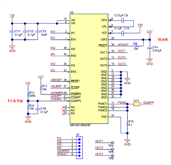
I have a question regarding the TIDA-00827 reference Design.

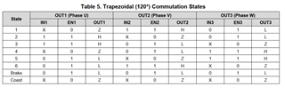
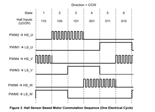
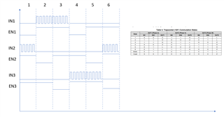
We would like to realize quite  similiar to the reference Design a trapezoidal control and would need to bring all EN on one pin of the micro.

my question is there a different firmware for this or is it the same like for the stepper motor TIDA-01362?

and when do i need seperated ENx for the control of the BLDC like at the TIDA-00274?

Hope you can help me thanks

Alex

  • Hi Alex,

    Please use the sensored trapezoidal firmware in TIDA-010056: https://www.ti.com/tool/TIDA-010056

    It should be the similar to TIDA-00827 and is written for MSP430 microcontrollers. 

    Thanks,
    Aaron

  • Hi Aaron,

    Thank you for your fast reply the TIDA-010056 is also very interesting but i think the not what i was looking for.

    Because it has 6 Signals 3 High and 3 Low Pins.

    But we would like to use the like to connect the DRV8313 like in the schematic below.

    But i think i could have problems regarding the commutation as shown in Table 5 of DRV8313 datasheet.

    I would assume that i have to control each ENABLE Pin independently.

    or is there a solution to commutated the motor with controlling all ENABLE Pins together with just one output??

    Thanks in advance

    Alex

  • Hello Aaron,

    I have another idea could you send me a scope picture of the TIDA-00827 with the 4 Input signal IN1,2,3 & EN and also the corresponding output signal??

    That would help a lot to understand this reference design.

    Best regards

    Alex

  • Hi Alex,

    You should not tie all ENABLE pins together because you need to Hi-Z some states when utilizing trapezoidal control. INx connects to 3 PWM outputs, and ENx connects to 3 GPIOs so PWM outputs toggle when ENx = 1. 

    We do not have TIDA-00827 on hand. 

    This is similar to "3x PWM" mode on many of our devices. I can share some C2000 code that does this in a newer, similar device called DRV8316 if requested. 

    Does this help?

    Thanks,
    Aaron

  • Hello Aaron,

    Yes this is quite helpful I think we're now on the right track.

    but how is this "3x PWM" working on the DRV8313 because on the DRV8316 there are no EN.

    you have INLx and  INHx with which you can quite easily realize the following pattern.

    I still don't get it when to switch the ENABLE Pins to achieve the Commutation pattern above.

    Because when i look at the table from the datasheet of the DRV8313 I assume that I can't achieve the pattern above.

    Do you have some App- Notes regardign the 3xPWM Mode and a diagram like in the Picture of the ENABLE and the PWMs.

    Thanks

    Alex

  • Hi Alex,

    I made a diagram of the ENx and INx signals for you based on DRV8313 datasheet. We have no app note for 3x PWM mode. 

    Think of ENx as INLx, and INx as INHx in 3x PWM mode. 

    • When ENx = 1 and INx = toggling PWM, the integrated MOSFETs synchronously switch and make OUTx go high at the duty cycle you're switching at. These are the "H" states for OUTx in the table. 
    • When ENx = 1 and INx = 0, the internal low-side MOSFET is on, so OUTx = 0. These are the "L" states for OUTx in the table. 
    • When ENx = 0, then the output is Hi-Z since both FETs are neither switched on or off. There are the "Z" states for OUTx in the table. 

    When using trapezoidal commutation, you'll want the right sequence of H, L, and Z as shown in the chart below to make the motor switch currents correctly, generate voltages at the stators to make the rotor spin, and commutate the motor efficiently/correctly. 

    Thanks,
    Aaron