This thread has been locked.

If you have a related question, please click the "Ask a related question" button in the top right corner. The newly created question will be automatically linked to this question.

TIDA-01504: TIDA-01504 Highly Accurate, Loop-Powered, 4- to 20-mA Field Transmitter With HART Modem Reference Design ,OPA V+ & V- can’t be equal

Part Number: TIDA-01504
Other Parts Discussed in Thread: OPA2335, DAC8742H

Hi , We are going to design a hardware for "Loop-Powered, 4- to 20-mA Field Transmitter With HART Modem" . I have a question hope someone can give a satisfying answer 

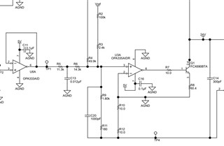
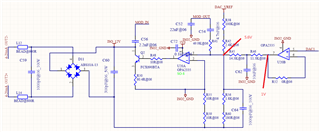
1.I used this circuit as pic, the only difference is that I replaced U6 & U3 with OPA2335, but now V+ & V- can’t be equal, is there any reason for this issues ?

  • Hi Han,

    Can you add some clarity to your question? Do you mean that V+ cannot be the same voltage as V-? Do you mean during shutdown mode?

  • Han,


    Looking at the specifications for the OPA2335, I don't see anything that would tell me that the replacement wouldn't work. The only thing that I see that is very different is that the OPA2335 has a smaller input common-mode range, where the inputs should be below V+ by at least 1.5V. Can you verify that the inputs are below this level?

    Also, I want to make sure that U6A is the device giving you problems. Based on your description, U3A is basically the same device as in the design notes. For your setup, which devices are off from expected (where - input and + input are not the same)? What voltages are they at when the circuit is in operation? What voltage is the output of the op-amp?


    Joseph Wu

  • HI Joseph,

                    Thank you for your reply, attachment is my circuit, DAC_VREF is 2.5V, DAC1 is 1V, in addition, my DAC8742H chip is not on board yet, according to datasheet of DAC8742H, U20A pin 2 & 3 should be 0V, but they are not the same. 

  • Han,

    I'm still not sure what the problem is. One possibility is a bad solder connection I would visually inspect the connections, just in case there was a problem in the manufacturing. 

    Can you please measure a couple of other voltages around the loop? I'm not sure where the 5.6V at the bottom of R43 comes from. There is nothing on that node that comes from a voltage greater than 5V. I would also measure the voltage the bottom of the loop (the voltage of the bottom of C60). How far below ground is that voltage? 

    Joseph Wu