Part Number: TIDM-02010
Other Parts Discussed in Thread: TMDSEMU200-U
Hi,
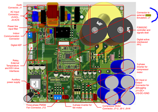
We have a evaluation board for motor control application i.e. TIDM-02010(Dual Motor Control with Digital Interleaved PFC for HVAC
Reference Design). We are trying to program it but not able to do it.
Details:
- Board: TIDM-02010
- Programmer : XDS200 Debug probe (TMDSEMU200-U) with TI14 adapter
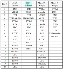
Since, the board only allows 2-pin cJTAG connections. We have done following connections.
- TMS(Board) to TMS(Debugger - pin 1)
- TCK(Board) to TCK(Debugger - pin 11)
- Gnd(Board) to Gnd(Debugger - pin 4)
- 3.3V(Board) to TVref(Debugger -pin 5)
Even after this, I am not able to program this chip. I tried test connection and I am getting following error.
[Start]
Execute the command:
%ccs_base%/common/uscif/dbgjtag -f %boarddatafile% -rv -o -S integrity
[Result]
-----[Print the board config pathname(s)]------------------------------------
C:\Users\piaoc\AppData\Local\TEXASI~1\CCS\
ccs1110\0\0\BrdDat\testBoard.dat
-----[Print the reset-command software log-file]-----------------------------
This utility has selected a 560/2xx-class product.
This utility will load the program 'xds2xxu.out'.
The library build date was 'Dec 8 2021'.
The library build time was '15:53:42'.
The library package version is '9.6.0.00172'.
The library component version is '35.35.0.0'.
The controller does not use a programmable FPGA.
An error occurred while hard opening the controller.
-----[An error has occurred and this utility has aborted]--------------------
This error is generated by TI's USCIF driver or utilities.
The value is '-183' (0xffffff49).
The title is 'SC_ERR_CTL_CBL_BREAK_FAR'.
The explanation is:
The controller has detected a cable break far-from itself.
The user must connect the cable/pod to the target.
[End]
Could someone help me resolving this issue?