This thread has been locked.

If you have a related question, please click the "Ask a related question" button in the top right corner. The newly created question will be automatically linked to this question.

PMP9774: Envelop signal generation

Part Number: PMP9774
Other Parts Discussed in Thread: TPS61088, , OPA4377

Hello,

Could you help two questions below? 

1. May I ask for more description on the generation of the envelop signal? I'm not sure why the two stage of buffers are required. What's the function of U3C?

My understanding so far is as below. There're four nodes in the schematic.
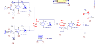
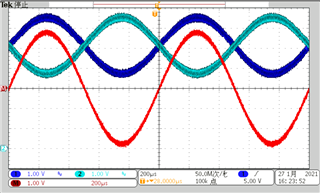
(1) Per the related thread, node 1 should be like ch 3 (red) of the waveform below. 
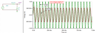
(2) For node 2, it would appear the same waveform with node 1. The only difference in waveform would come from the LPF with Fco 13.16kHz, passing the sinusoidal signal with <Fco and some distortion in amplitude and phase for the signal > Fco.
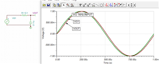
(3) For node 3, it would be same waveform with node 2. Why is U3C required?
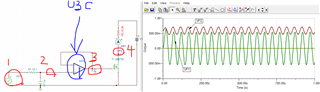
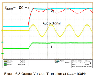
2. I notice the Vo is not actually tracking the audio signal. What I expected looks like red trace if the response is fast enough. Where does this slow response come from? Maybe from the converter's (TPS61088) narrow control loop BW?
I'm looking for the envelop tracking solution for RF, not for AF, upto several MHz. I'm wondering if PMP9774 design concept would work for this high frequency. 

Thank you for helping my understanding! Thanks.

  • Hi Ella,

    1. U3C and Q1 convert the envelope voltage signal to an envelope current signal. This envelope current signal makes the output voltage of the TPS61088 changes in accordance with the amplitude of the input audio signal. 

    2. The output voltage can track the audio signal well at about hundred Hz, the waveform is not very clear because it has 10V DC bias. I am afraid it cannot track MHz, because the switching frequency is 2MHz (max) and bandwidth is about 10kHz. But I am not very familiar with BW and RF system, maybe if you have any other opinions on tracking RF signal with 2MHz (switching frequency) and 50kHz (bandwidth) system?

    Best Regards,

    Eric Yue

  • Hi Eric,

    Thank you for comment. I think I need to separate the implementation of envelop signal from SMPS. SMPS cannot track MHz as it has limited loop bandwidth.

    If we assume we have a hypothetical SMPS with a wide BW (say 10MHz), I wonder if U3A/B/C/D/Q1 circuitry still can generate the valid envelop signal for RF signal (upto 2MHz). What I'm concerning is the delay from the U3A/B/C/D/Q1 circuitry. For envolop tracking, the power supply output actually should come ahead of RF input signal. But if U3A/B/C/D/Q1 circuitry makes delay, SMPS output would come after RF input signal, which is a problem.

    For AF, the delay might not be a matter, but I believe it matters for the higher frequency RF signal. Could you advise how I can estimate the delay from the U3A/B/C/D/Q1 circuitry? Maybe should I look into GBW or SR spec of OPAMP?

  • Hi Ella,

    I think U3A/B/C/D/Q1 will have some delay because of the limited bandwidth. But I am not familiar with amplifier and BW. Maybe you can create one more threat to ask for expert responsible for OPA4377 for help. 

    Best Regards,

    Eric Yue