This thread has been locked.

If you have a related question, please click the "Ask a related question" button in the top right corner. The newly created question will be automatically linked to this question.

Modeling N-Channel MOSFET

Other Parts Discussed in Thread: INA149, CSD13383F4, TINA-TI

I am attempting to create a battery monitor reference design for space applications. 

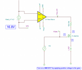
I would like to add an N-channel MOSFET to the output of a differential amplifier in order to leave the circuit open when I am not reading the voltage. I have added a snippet of my circuit below. My challenge: weather the FET is open or closed, I always see 5.2V at the output of the INA149. I would like to see a high Z state art Vout_4 when T1 is open and 5.2V when T1 is closed.

Feel free to ask any questions for clarification.

Thank you, 

Lucas M. Pucheta

Systems Engineer | Aerospace & Defense


 Vbatt Sensing INA149 V3.TSC

  • Hello Lucas,

    Thanks for the inquiry. The FET is really not doing much for you. When it's ON, the voltage at the drain and source are approximately equal (0V) and the current thru R24 = Vout_4/33kΩ. When the FET is OFF, no current flows thru R24 and Vout_4 = 5.2V. You want to place the FET in series with the output of the diff amp and take your output off the source of the FET. I'd suggest moving R24 and connecting it from the source to GND. Because the drain voltage and source voltage are about the same when it is on, you will have to drive the gate higher than the output of your diff amp. I pulled up the datasheet for the FET you selected and it's very old part (TINA-TI has some old parts in the library). On resistance is specified at VGS = 10V so you will want to make VG at least 15V to make sure it is fully enhanced. By the way, we have unencrypted PSpice models for all of our FETs on TI.com and you can create a macro if you want to use a more modern FET in your simulation. Any of our low voltage (<=30V) NFET should work. I modified your circuit, used the CSD13383F4 as the FET and set the DC voltage of VG to 8V. I ran a DC simulation and I get 7.22V at Vout_4. See attached. Shoot me an email if you have any questions.

    Thanks,

    John Wallace

    TI FET Applications

    Vbatt Sensing INA149 V3-1 new FET.TSC

  • Thank you John, this was a tremendous help.