


Part Number: TIDA-00080
Other Parts Discussed in Thread: AMC1306EVM, C2000WARE, CDCE906, AMC1306M25
Good morning.
I was wondering if I can get some advice about the problem I meet with.
The final goal is to operate the TIDA-00080 reference design.
First, I tried to investigate the performance with AMC1306EVM.
I used the clock signal that I made from PWM in MCU(F280049).
I also used the modified example code for the SDFM (C2000Ware_4_01_00_00\driverlib\f28004x\examples\sdfm\sdfm_ex1_filter_sync_cpuread.c)
In this case, I could see the clock signal, data signal, and filter results on CCS debug.
Second, I have investigated the TIDA-00080 design. I got the PCB from the file, and most of the components were assembled(not including the FPGA part)
Also reconfigured the CDCE906 register and I could get the clock signal from there.
At this moment, I could see the clock signal as an input of the AMC1306, and the Data signal as an output of the AMC1306 ic chip.
Here is the waveform that I get.
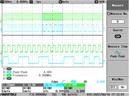
The green pulse is the clock signal on pin 7(CLKIN on AMC1306M25), 10[MHz]
The blue pulse is the data signal on pin 6(DOUT on AMC1306M25)
In the summary, I can get the proper signal on the SDFM side.
The problem is on the MCU side. I couldn't get the filter result on debug session. It is shown that the value of all 0.
So I investigated the code and then I could get the flag on MF1 is set.
In the technical reference manual, it is said that "Modulator failures (MFx) are generated when SD-Cx goes missing."
I checked the GPBDAT/GPIO49 which I assigned as a SD1_C1, and I could see the alternating value(0 to 1) in real-time.
So I thought "the clock is not missing". But still, the MF1 bit is set and stuck at that(Line 329 on the code I attached) point.
I could find the thread related to this problem on "e2e.ti.com/.../tms320f28379d-using-sdfm-with-amc1305-evm"
But the author of that thread used the PWM as a clock signal. But I have used an external signal so I couldn't follow the solution on that thread.
In this case, what can I check for the proper interrupt of SDFM?
I attached the code below for your information. I didn't use the GUI and Firmware for the TIDA-00080 cause I don't need that function.
Thank you for your help.
Regards.
//###########################################################################
//
// FILE:   sdfm_ex1_filters.c
//
// TITLE:  SDFM Filter sync CPU Example.
//
//! \addtogroup driver_example_list
//! <h1> SDFM Filter Sync CPU</h1>
//!
//! In this example, SDFM filter data is read by CPU in SDFM ISR routine. The
//! SDFM configuration is shown below:
//!  -  SDFM used in this example - SDFM1
//!  -  Input control mode selected - MODE0
//!  -  Comparator settings
//!       - Sinc3 filter selected
//!       - OSR = 32
//!       - HLT = 0x7FFF (Higher threshold setting)
//!       - LLT  = 0x0000(Lower threshold setting)
//!  -  Data filter settings
//!      - All the 4 filter modules enabled
//!      - Sinc3 filter selected
//!      - OSR = 128
//!      - All the 4 filters are synchronized by using MFE
//!       (Master Filter enable bit)
//!      - Filter output represented in 16 bit format
//!      - In order to convert 25 bit Data filter
//!        into 16 bit format user needs to right shift by 8 bits for
//!        Sinc3 filter with OSR = 128
//!  - Interrupt module settings for SDFM filter
//!      - All the 4 higher threshold comparator interrupts disabled
//!      - All the 4 lower threshold comparator interrupts disabled
//!      - All the 4 modulator failure interrupts disabled
//!      - All the 4 filter will generate interrupt when a new filter data
//!        is available.
//!
//
//###########################################################################
//
// $Release Date: $
// $Copyright:
// Copyright (C) 2013-2022 Texas Instruments Incorporated - http://www.ti.com/
//
// Redistribution and use in source and binary forms, with or without
// modification, are permitted provided that the following conditions
// are met:
//
//   Redistributions of source code must retain the above copyright
//   notice, this list of conditions and the following disclaimer.
//
//   Redistributions in binary form must reproduce the above copyright
//   notice, this list of conditions and the following disclaimer in the
//   documentation and/or other materials provided with the
//   distribution.
//
//   Neither the name of Texas Instruments Incorporated nor the names of
//   its contributors may be used to endorse or promote products derived
//   from this software without specific prior written permission.
//
// THIS SOFTWARE IS PROVIDED BY THE COPYRIGHT HOLDERS AND CONTRIBUTORS
// "AS IS" AND ANY EXPRESS OR IMPLIED WARRANTIES, INCLUDING, BUT NOT
// LIMITED TO, THE IMPLIED WARRANTIES OF MERCHANTABILITY AND FITNESS FOR
// A PARTICULAR PURPOSE ARE DISCLAIMED. IN NO EVENT SHALL THE COPYRIGHT
// OWNER OR CONTRIBUTORS BE LIABLE FOR ANY DIRECT, INDIRECT, INCIDENTAL,
// SPECIAL, EXEMPLARY, OR CONSEQUENTIAL DAMAGES (INCLUDING, BUT NOT
// LIMITED TO, PROCUREMENT OF SUBSTITUTE GOODS OR SERVICES; LOSS OF USE,
// DATA, OR PROFITS; OR BUSINESS INTERRUPTION) HOWEVER CAUSED AND ON ANY
// THEORY OF LIABILITY, WHETHER IN CONTRACT, STRICT LIABILITY, OR TORT
// (INCLUDING NEGLIGENCE OR OTHERWISE) ARISING IN ANY WAY OUT OF THE USE
// OF THIS SOFTWARE, EVEN IF ADVISED OF THE POSSIBILITY OF SUCH DAMAGE.
// $
//###########################################################################

//
// Included Files
//
#include "driverlib.h"
#include "device.h"
#include <stdio.h>

//
// Defines
//
#define MAX_SAMPLES               1024
//
// Globals
//

int16_t  filter1Result[MAX_SAMPLES];
int16_t  filter2Result[MAX_SAMPLES];
int16_t  filter3Result[MAX_SAMPLES];
int16_t  filter4Result[MAX_SAMPLES];
#pragma DATA_SECTION(filter1Result, "Filter1_RegsFile");
#pragma DATA_SECTION(filter2Result, "Filter2_RegsFile");
#pragma DATA_SECTION(filter3Result, "Filter3_RegsFile");
#pragma DATA_SECTION(filter4Result, "Filter4_RegsFile");

//
// Defines
//
#define SDFM_FILTER_ENABLE 0x2U

//
// Function Prototypes
//
void configureSDFMPins(void);
void done(void);
__interrupt void sdfm1ISR(void);
__interrupt void sdfm2ISR(void);


//
// Main
//
void main(void)
{
    uint16_t  hlt, llt;

    //
    // Initialize device clock and peripherals
    //
    Device_init();

    //
    // Setup GPIO by disabling pin locks and enabling pullups
    //
    Device_initGPIO();

    //
    // Initialize PIE and clear PIE registers. Disables CPU interrupts.
    //
    Interrupt_initModule();

    //
    // Initialize the PIE vector table with pointers to the shell Interrupt
    // Service Routines (ISR).
    //
    Interrupt_initVectorTable();

    //
    // Interrupts that are used in this example are re-mapped to
    // ISR functions found within this file.
    //
    Interrupt_clearACKGroup(INTERRUPT_ACK_GROUP5);
    Interrupt_register(INT_SD1, sdfm1ISR);
    Interrupt_register(INT_SD2, sdfm2ISR);

    //
    // Enable SDFM1 amd SDFM2 interrupts
    //
    Interrupt_enable(INT_SD1);
    Interrupt_enable(INT_SD2);

    //
    // Input Control Unit
    //
    // Configure Input Control Unit: Modulator Clock rate = Modulator data rate
    //
    SDFM_setupModulatorClock(SDFM1_BASE, SDFM_FILTER_1,
                             SDFM_MODULATOR_CLK_EQUAL_DATA_RATE);

    SDFM_setupModulatorClock(SDFM1_BASE, SDFM_FILTER_2,
                             SDFM_MODULATOR_CLK_EQUAL_DATA_RATE);

    SDFM_setupModulatorClock(SDFM1_BASE, SDFM_FILTER_3,
                             SDFM_MODULATOR_CLK_EQUAL_DATA_RATE);

    SDFM_setupModulatorClock(SDFM1_BASE, SDFM_FILTER_4,
                             SDFM_MODULATOR_CLK_EQUAL_DATA_RATE);

    //
    // Comparator Unit - over and under value threshold settings
    //
    hlt = 0x7FFF;
    llt = 0x0000;

    //
    // Configure Comparator Unit's comparator filter type and comparator's
    // OSR value, higher threshold, lower threshold
    //
    SDFM_configComparator(SDFM1_BASE,
        (SDFM_FILTER_1 | SDFM_FILTER_SINC_3 | SDFM_SET_OSR(32)),
        (SDFM_GET_LOW_THRESHOLD(llt) | SDFM_GET_HIGH_THRESHOLD(hlt)));
    SDFM_configComparator(SDFM1_BASE,
        (SDFM_FILTER_2 | SDFM_FILTER_SINC_3 | SDFM_SET_OSR(32)),
        (SDFM_GET_LOW_THRESHOLD(llt) | SDFM_GET_HIGH_THRESHOLD(hlt)));
    SDFM_configComparator(SDFM1_BASE,
        (SDFM_FILTER_3 | SDFM_FILTER_SINC_3 | SDFM_SET_OSR(32)),
        (SDFM_GET_LOW_THRESHOLD(llt) | SDFM_GET_HIGH_THRESHOLD(hlt)));
    SDFM_configComparator(SDFM1_BASE,
        (SDFM_FILTER_4 | SDFM_FILTER_SINC_3 | SDFM_SET_OSR(32)),
        (SDFM_GET_LOW_THRESHOLD(llt) | SDFM_GET_HIGH_THRESHOLD(hlt)));

    //
    // Data Filter Unit
    //
    // Configure Data Filter Unit - filter type, OSR value and
    // enable / disable data filter
    //
    SDFM_configDataFilter(SDFM1_BASE, (SDFM_FILTER_1 | SDFM_FILTER_SINC_3 |
           SDFM_SET_OSR(128)), (SDFM_DATA_FORMAT_16_BIT | SDFM_FILTER_ENABLE |
           SDFM_SHIFT_VALUE(0x0007))); //0x0008

    SDFM_configDataFilter(SDFM1_BASE, (SDFM_FILTER_2 | SDFM_FILTER_SINC_3 |
           SDFM_SET_OSR(128)), (SDFM_DATA_FORMAT_16_BIT | SDFM_FILTER_ENABLE |
           SDFM_SHIFT_VALUE(0x0007)));

    SDFM_configDataFilter(SDFM1_BASE, (SDFM_FILTER_3 | SDFM_FILTER_SINC_3 |
           SDFM_SET_OSR(128)), (SDFM_DATA_FORMAT_16_BIT | SDFM_FILTER_ENABLE |
           SDFM_SHIFT_VALUE(0x0007)));

    SDFM_configDataFilter(SDFM1_BASE, (SDFM_FILTER_4 | SDFM_FILTER_SINC_3 |
           SDFM_SET_OSR(128)), (SDFM_DATA_FORMAT_16_BIT | SDFM_FILTER_ENABLE |
           SDFM_SHIFT_VALUE(0x0007)));

    //
    // Enable Master filter bit: Unless this bit is set none of the filter modules
    // can be enabled. All the filter modules are synchronized when master filter
    // bit is enabled after individual filter modules are enabled.
    //
    SDFM_enableMasterFilter(SDFM1_BASE);

    //
    // PWM11.CMPC, PWM11.CMPD, PWM12.CMPC and PWM12.CMPD signals cannot synchronize
    // the filters. This option is not being used in this example.
    //
    SDFM_disableExternalReset(SDFM1_BASE, SDFM_FILTER_1);
    SDFM_disableExternalReset(SDFM1_BASE, SDFM_FILTER_2);
    SDFM_disableExternalReset(SDFM1_BASE, SDFM_FILTER_3);
    SDFM_disableExternalReset(SDFM1_BASE, SDFM_FILTER_4);

    //
    // Enable interrupts
    //
    // Following SDFM interrupts can be enabled / disabled using this function.
    // Enable / disable comparator high threshold
    // Enable / disable comparator low threshold
    // Enable / disable modulator clock failure
    // Enable / disable data filter acknowledge
    //
    SDFM_enableInterrupt(SDFM1_BASE, SDFM_FILTER_1,
            (SDFM_MODULATOR_FAILURE_INTERRUPT |
             SDFM_DATA_FILTER_ACKNOWLEDGE_INTERRUPT));
/*
    SDFM_enableInterrupt(SDFM1_BASE, SDFM_FILTER_2,
            (SDFM_MODULATOR_FAILURE_INTERRUPT |
             SDFM_DATA_FILTER_ACKNOWLEDGE_INTERRUPT));

    SDFM_enableInterrupt(SDFM1_BASE, SDFM_FILTER_3,
            (SDFM_MODULATOR_FAILURE_INTERRUPT |
             SDFM_DATA_FILTER_ACKNOWLEDGE_INTERRUPT));

    SDFM_enableInterrupt(SDFM1_BASE, SDFM_FILTER_4,
            (SDFM_MODULATOR_FAILURE_INTERRUPT |
             SDFM_DATA_FILTER_ACKNOWLEDGE_INTERRUPT));
*/
    SDFM_disableInterrupt(SDFM1_BASE, SDFM_FILTER_1,
            (SDFM_HIGH_LEVEL_THRESHOLD_INTERRUPT |
             SDFM_LOW_LEVEL_THRESHOLD_INTERRUPT));

    SDFM_disableInterrupt(SDFM1_BASE, SDFM_FILTER_2,
            (SDFM_HIGH_LEVEL_THRESHOLD_INTERRUPT |
             SDFM_LOW_LEVEL_THRESHOLD_INTERRUPT));

    SDFM_disableInterrupt(SDFM1_BASE, SDFM_FILTER_3,
            (SDFM_HIGH_LEVEL_THRESHOLD_INTERRUPT |
             SDFM_LOW_LEVEL_THRESHOLD_INTERRUPT));

    SDFM_disableInterrupt(SDFM1_BASE, SDFM_FILTER_4,
            (SDFM_HIGH_LEVEL_THRESHOLD_INTERRUPT |
             SDFM_LOW_LEVEL_THRESHOLD_INTERRUPT));

    //
    // Enable master interrupt so that any of the filter interrupts can trigger
    // by SDFM interrupt to CPU
    //
    SDFM_enableMasterInterrupt(SDFM1_BASE);

    //
    // Enable Global Interrupt (INTM) and realtime interrupt (DBGM)
    //
    EINT;
    ERTM;

    //
    // Wait for an interrupt
    //
    while(1);
}

//
// sdfm1ISR - SDFM 1 ISR
//
__interrupt void sdfm1ISR(void)
{

    static uint16_t loopCounter1 = 0;

    SDFM_setOutputDataFormat(SDFM1_BASE, SDFM_FILTER_1,
                             SDFM_DATA_FORMAT_16_BIT);

    SDFM_setOutputDataFormat(SDFM1_BASE, SDFM_FILTER_2,
                             SDFM_DATA_FORMAT_16_BIT);

    SDFM_setOutputDataFormat(SDFM1_BASE, SDFM_FILTER_3,
                             SDFM_DATA_FORMAT_16_BIT);

    SDFM_setOutputDataFormat(SDFM1_BASE, SDFM_FILTER_4,
                             SDFM_DATA_FORMAT_16_BIT);

    if(loopCounter1 >= MAX_SAMPLES)
       {
           //
           // Reset the counter. Add breakpoint at below statement to view the
           // filter results in graph view.
           //
           loopCounter1 = 0;

   //        //
   //        // Software breakpoint to view results.
   //        // Hit run again to get updated conversions.
   //        // Uncomment to halt the execution once buffer is full.
   //        //
   //        ESTOP0;
       }
    //
    // Read SDFM flag register (SDIFLG)
    //

    while((HWREG(SDFM1_BASE + SDFM_O_SDIFLG) & 0x1000) != 0x1000) //0xF000U
    {
    }
        //
        // Read each SDFM filter output and store it in respective filter
        // result array
        //
        filter1Result[loopCounter1] =
              (int16_t)(SDFM_getFilterData(SDFM1_BASE, SDFM_FILTER_1) >> 16U);

        filter2Result[loopCounter1] =
              (int16_t)(SDFM_getFilterData(SDFM1_BASE, SDFM_FILTER_2) >> 16U);

        filter3Result[loopCounter1] =
              (int16_t)(SDFM_getFilterData(SDFM1_BASE, SDFM_FILTER_3) >> 16U);

        filter4Result[loopCounter1++] =
              (int16_t)(SDFM_getFilterData(SDFM1_BASE, SDFM_FILTER_4) >> 16U);

        //
        // Clear SDFM flag register (SDIFLG)
        //
        SDFM_clearInterruptFlag(SDFM1_BASE, SDFM_MASTER_INTERRUPT_FLAG |
                                            0xFFFF);

    //
    // Acknowledge this __interrupt to receive more __interrupts from group 5
    //
    Interrupt_clearACKGroup(INTERRUPT_ACK_GROUP5);
}

//
// sdfm2ISR - SDFM 2 ISR
//
__interrupt void sdfm2ISR(void)
{
    uint32_t sdfmReadFlagRegister = 0;
    static uint16_t loopCounter1 = 0;

    SDFM_setOutputDataFormat(SDFM2_BASE, SDFM_FILTER_1,
                             SDFM_DATA_FORMAT_16_BIT);

    SDFM_setOutputDataFormat(SDFM2_BASE, SDFM_FILTER_2,
                             SDFM_DATA_FORMAT_16_BIT);

    SDFM_setOutputDataFormat(SDFM2_BASE, SDFM_FILTER_3,
                             SDFM_DATA_FORMAT_16_BIT);

    SDFM_setOutputDataFormat(SDFM2_BASE, SDFM_FILTER_4,
                             SDFM_DATA_FORMAT_16_BIT);

    //
    // Read SDFM flag register (SDIFLG)
    //
    sdfmReadFlagRegister = HWREG(SDFM2_BASE + SDFM_O_SDIFLG);

    if(loopCounter1 < MAX_SAMPLES)
    {
        //
        // Read each SDFM filter output and store it in respective filter
        // result array
        //
        filter1Result[loopCounter1] =
                (int16_t)SDFM_getFilterData(SDFM2_BASE, SDFM_FILTER_1);

        filter2Result[loopCounter1] =
                (int16_t)SDFM_getFilterData(SDFM2_BASE, SDFM_FILTER_2);

        filter3Result[loopCounter1] =
                (int16_t)SDFM_getFilterData(SDFM2_BASE, SDFM_FILTER_3);

        filter4Result[loopCounter1++] =
                (int16_t)SDFM_getFilterData(SDFM2_BASE, SDFM_FILTER_4);

        //
        // Clear SDFM flag register
        //
        SDFM_clearInterruptFlag(SDFM2_BASE,
                                (SDFM_MASTER_INTERRUPT_FLAG | 0xFFFF));

        sdfmReadFlagRegister = HWREG(SDFM2_BASE + SDFM_O_SDIFLG);

        if(sdfmReadFlagRegister != 0x0)
        {
            ESTOP0;
        }
    }
    else
    {
        ESTOP0;
        done();
    }

    //
    // Acknowledge this __interrupt to receive more __interrupts from group 5
    //
    Interrupt_clearACKGroup(INTERRUPT_ACK_GROUP5);
}

//
// configureSDFMPins - Configure SDFM GPIOs
//
void configureSDFMPins(void)
{
    uint16_t pin;
    for(pin = 48; pin <= 55; pin++)
    {
        GPIO_setDirectionMode(pin, GPIO_DIR_MODE_IN);
        GPIO_setMasterCore(pin, GPIO_CORE_CPU1);
        GPIO_setPadConfig(pin, GPIO_PIN_TYPE_STD);
        GPIO_setQualificationMode(pin, GPIO_QUAL_ASYNC);
    }

    GPIO_setPinConfig(GPIO_48_SD1_D1);
    GPIO_setPinConfig(GPIO_49_SD1_C1);
    GPIO_setPinConfig(GPIO_50_SD1_D2);
    GPIO_setPinConfig(GPIO_51_SD1_C2);
    GPIO_setPinConfig(GPIO_52_SD1_D3);
    GPIO_setPinConfig(GPIO_53_SD1_C3);
    GPIO_setPinConfig(GPIO_54_SD1_D4);
    GPIO_setPinConfig(GPIO_55_SD1_C4);
    /*
    for(pin = 28; pin <= 29; pin++)
    {
        GPIO_setDirectionMode(pin, GPIO_DIR_MODE_IN);
        GPIO_setMasterCore(pin, GPIO_CORE_CPU1);
        GPIO_setPadConfig(pin, GPIO_PIN_TYPE_STD);
        GPIO_setQualificationMode(pin, GPIO_QUAL_ASYNC);
    }
    GPIO_setPinConfig(GPIO_28_SD2_D3);
    GPIO_setPinConfig(GPIO_29_SD2_C3);
    */
}

//
// done - Function to halt debugger and stop application
//
void done(void)
{
    asm(" ESTOP0");
    for(;;);
}


//
// End of file
//
