Hi Team,
Can you please help us with our customer's inquiry below.
Regards,
Danilo
This thread has been locked.
If you have a related question, please click the "Ask a related question" button in the top right corner. The newly created question will be automatically linked to this question.
Hi Team,
Can you please help us with our customer's inquiry below.
Regards,
Danilo
Hi, Danilo,
When in steady state there is a DC bias on the capacitor in series with the secondary winding. This DC bias is equal to 1/2 the output voltage. During the positive 1/2 cycle the top and bottom FET turn on current and is delivered to the 2 output capacitors in series. During the negative 1/2 cycle the middle 2 FETs turn on to reset the magnetics and the blocking capacitor voltage.
When operating with a series stack bridge on the secondary, the secondary does not need active voltage balancing.
Best regards,
Brent
Hi Brent,
Please see the response of our customer below.
Many thanks for the kindness to response my inquiry! But I still have some questions and hope to receive your reply.
As you said, the DC bias voltage is equal to 1/2 the output voltage, and the DC bias voltage is delivered to the two output capacitors in series during the positive half cycle. For the 800V output voltage on-board charger, it means that 400V charges the two capacitors in series, and each capacitor have 200V, as shown in the figure. The output voltage becomes 400V rather than 800V in this state. Is there something I misunderstand?
From my knowledge, the CLLLC can achieve ZVS on the primary side and ZCS on the secondary side, which means that the current in the secondary side will return to zero before the end of the half cycle, as the current waveform shown in the full-bridge CLLLC figure. So, can you illustrate the meaning of ''reset the magnetics'' in more detail? Or, can you provide the current waveform like the CLLLC figure for me to understand?
Regards,
Danilo
Hi, Danilo,
The series capacitors each get charged with 400V. The cap in series with the secondary winding also charges to 400V.
Saying "reset the magnetics" was probably the wrong way to describe it. The transformer secondary produces an AC current. When the outer switches are on this current is positive. When the inner switches are on this current is negative.

I hope that helps.
Best regards,
Brent
Hi Brent,
Here is the feedback of our customer.
Many thanks for the kindness to response my inquiry!
Does it mean that the voltage of the secondary side is 800V? So, each capacitor in series can charge to 400V, as shown in the figure.
The inner switches are on in the negative cycle. It looks like a short circuit on the secondary side. How to keep the same peak current as a positive half cycle? Doesn't it produce a substantial short current through inner FETs?
Regards,
Danilo
Hi, Danilo,
It's not a short circuit on the secondary since there is the secondary side inductance in series with the short. In principle this is no different than when the outer switches are on.
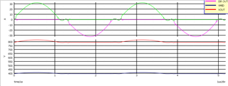
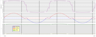
The transformer secondary voltage is shown in the following plot.

Hi Brent,
According to our customer,
Thanks for your reply! I have understood the principle of this topology in charging time. I wonder to know that how the switches operate on the secondary side during discharge time. Is the operation of switches is same as the charging time? Or, only one of the capacitors is discharging and the two capacitors take turns to discharge?
Since there are two half-bridge in series on the secondary side, does it means that only a positive half cycle is used to provide power to the grid?
Regards,
Danilo
The converter has a few different modes of operation. However, in a normal operation mode the switch sequence would essentially be the same as I described above.
So yes, essentially power is only delivered during one 1/2 cycle.
Hi Brent,
Please see the comment of our customer below.
Many thanks for your patient reply. I still have some questions and hope to receive your valuable answer.
If the switch sequence is the same as the charging state, does it means that the battery voltage 800V will be transferred to the primary side? Since the transformer ratio is the same as the charging state. However, the devices used for this system are all 650V. Will the switches not be damaged? Or is there something I misunderstand?
Regards,
Danilo
Hi, Danilo,
It depends on how the system was designed. You can have a 800V to 800V converter or you could also do 400V to 800V. I assume your interest is in the latter case, although the principles are identical. When the converter runs to transfer power from the 800V batter to the 400V inverter the secondary side capacitor in series with the winding strips off 1/2 of the output voltage. Thus the transformer sees only 400V on the secondary. The primary voltage scales this by turns ratio. Therefore 650V FETs will work fine.
Best regards,
Brent