Hello there,
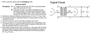
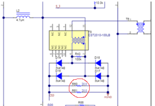
I saw a resistor between seconder side of current transformer. I was wondering the reason for using this. Could you please explain this.
Hello there,
I saw a resistor between seconder side of current transformer. I was wondering the reason for using this. Could you please explain this.