


Other Parts Discussed in Thread: TIDA-010208,
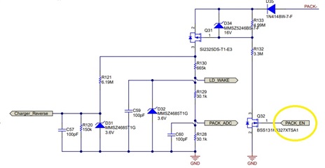
I have taken this reference circuit from https://www.ti.com/tool/TIDA-010216. I want to know that in which condition PACK EN is high or low means the MOSFET Q32 will be ON / OFF.
I have taken this reference circuit from https://www.ti.com/tool/TIDA-010216. I want to know that in which condition PACK EN is high or low means the MOSFET Q32 will be ON / OFF.

