This thread has been locked.

If you have a related question, please click the "Ask a related question" button in the top right corner. The newly created question will be automatically linked to this question.

TIDA-010057: TIDA-010057

Part Number: TIDA-010057
Other Parts Discussed in Thread: TX7332,

Hello, every one,

I use SWAROOP+ TIDA-010057 handheld ultrasound project, when debugging with an oscilloscope can be tested to TX7332 output pulse, while running HSDC ProGUI can not capture data, I do not know why? My steps are as follows;

1. Connect SWAROOP and TIDA-010057;

2. Connecting USB and JTAG;

3. Power on and run the HSDC Pro GUI;

4. Initializing equipment;

5. Set the number of TX and RX channels;

6.pressconfiguresystembutton;

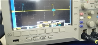
7. Measure the JP1 point of SWAROOP and TX7332HV output pulse with oscilloscope. The measured waveform is shown in the following figures;

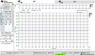
8. Click the capture button, as shown in the following figure, but no waveform is read;

9. The voltage of TIDA-010057 is normal;

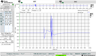
10. If I replace a piece of TIDA-010057 and run the above 9 steps, the data can be captured, as shown in the following figure;

11. What is the reason for this? How do I find the cause of the defect?

Thank you!

Best wishes!

Chime Xia

  • Hi Chime, 

    We have received your request. Give us a few days to evaluate it. We will get back to you by Thursday, Feb 9. 

    Thanks for your patience. 

    Karthik

  • Hi Chime,

    Can you elaborate the yellow and blue waveform on the oscilloscope? I am assuming that the yellow is the TX7332 output pattern.

    The voltage levels also looks fine to me.

    On point 10, when you say you replace piece of TIDA-010057, what do you mean by that? What are you replacing? 

    Since you are getting all 0s as your output? Would it be possible for you to disconnect the High Voltage Supply from the path and check the capture. For disabling high voltage supply, you can remove the zero ohm resistor (R54) at the input of the HV supply. 

    Thanks & regards,

    Abhishek

  • Hi Abhishek,

    Thank you for your reply!

    Recently, I was researching CYUSB3014, so I didn't reply you in time.

    The yellow waveform mentioned in clause 10 is the output of the TX7332. The blue waveform is the sync signal. I have 3 TIDA-010057 power strips, 1 of which is good and the other 2 are bad. I just use the good one to replace it, just to verify whether the bad power board or the imaging board.

    After scanning the bad TIDA-010057, it was preliminarily determined that it was caused by CYUSB3014 false soldering.

    I'm still analyzing the bad, and I'll tell you if there is any progress. I also hope to get your further guidance. 

    Thanks $ regards,

    Chime

  • Hi Chime,

    Yes, please do share your observations and let me know if there are any questions.

    Shall await for your response.

    Thanks & regards,

    Abhishek