This thread has been locked.

If you have a related question, please click the "Ask a related question" button in the top right corner. The newly created question will be automatically linked to this question.

PSPICE-FOR-TI: Logic control signal for TMUX IC

Part Number: PSPICE-FOR-TI
Other Parts Discussed in Thread: TMUX8108, TMUX8109, TMUX1122,

Hi team,

One of our customer's issues, I'm forwarding it below, please give your comments if any.

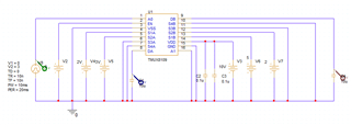
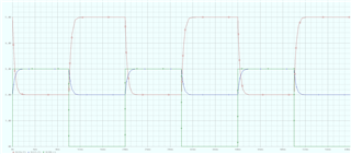
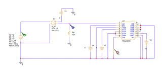
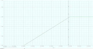
It is currently expected to use TMUX1122, TMUX8108, TMUX8109 three component application circuits, so PSPICE-FOR-TI simulation first. I would like to ask you in PSPICE-FOR-TI which type logic control signal of TMUX are used by all? The fixed voltage (5C or 0V) simulation behavior is correct when running PSPICE-FOR-TI simulation, but the switch control still stuck in the place of the switch. I have used the STIM digital signal, VPULSE analog signal, VPWL voltage source are all the same, it will get stuck when switching on and off. Or where do I need to pay attention to the settings of my simulation? Any troubleshooting ideas are appreciated.

Best Regards,

Amy Luo

  • Hey Amy,

    Can you share the schematic circuits? If i'm understanding correctly, the voltage on the control pins is either 0V or 5V. This should be sufficient for changing the logic of all three devices. These are all 1.8V logic compatible so a voltage lower than 0.8V will be read as low and a voltage above 1.3V will be read as a high. 
    Looking at the models though, I will also note that the TMUX1122 model is an older version of our current models and states that it only operates if the VCC is between 4.9 and 5.1V. Otherwise, they may be seeing witching errors from the model.

    Thanks,
    Rami

  • Hi Rami,

    Thank you for your reply. 

    I'm sorry, I don't seem to have described the customer's issue clearly, I would like to add the customer's issue as follows, and I would like you to provide some guidance.

    Figure 1 shows the schematic circuit for TMUX8109

    https://photos.app.goo.gl/uG1QrFBnJ6meQpfPA

    Figure 2 is the successful waveform for file and Pspice that controls the signal

    https://photos.app.goo.gl/wbbTqW363p2kAcFF7

    Figure 3 is the failed waveform for file and Pspice that controls the signal

    https://photos.app.goo.gl/mQPjbMRkabdct4xt7

    Success and failed pictures have the file content of the control signal ~

    Success: The original signal is maintained for 10ms, so the simulation is successful

    Failed : Change the control signal of A0 pin from 1 to 0 at 10ms, simulated at 10ms jam will occur

    Conclusion, Pspice will be stuck when the control signal of the A0 pin of TMUX8109 is converted.

    Best Regards,

    Amy

  • Hey Amy, 

    Do you know the rise/fall times of the A0 signal during the transition? I believe what's happening is that the R/F times are too slow so part of the simulation is run inbetween the VIH and VIL, which will cause some convergence errors and the model will fail. In between VIH and VIL the switch is an unknown state so the model here is also unknown and will shoot out an error instead of trying to give a random output. 

    That being said, I didn't seem to have a problem with simulating during a transition if I sped up the R/F times. 
      

    I played around with it a bit and the slowest I found the r/f times could be before a convergence error was 200ns. Anything above it and the model would get stuck in the 'inbetween' state and error out. 

    Can they possible change the rise/fall times? In real life, they have a lot more margin for switching r/f speeds but for the model they may need to just speed it up a bit.

    Thanks,
    Rami

  • Hi Rami,

    Thank you very much for your analysis above.

    The customer says that it is possible to use a VPULSE power supply to simulate (as you said to adjust TR/TF time), but only the VPULSE power supply can adjust TR/TF time. Later I used VPWL_F_RE_N_TIMES to use the following format, I could barely let Pspice simulate it. Can the source of the signal described by "File-input" also adjust the TR/TF time?

    0ms        0
    3ms        0
    3.001ms 3
    6ms        3
    6.001ms 0
    9ms        0
    9.001ms 3

    Regards,

    Amy

  • Hi Rami,

    I would like to clarify the customer's issue. The customer would like to ask if there are any other "File-input" sources that can adjust TR/TF time besides the VPULSE Source?

    Thanks,

    Amy

  • Hey Amy,

    I'm not sure what a 'file-input' source is. Can you provide more information or background on this?
    Sounds like though you're saying they can't configure the rise/fall times with their current source, correct?

    For simulation purposes, could they implement some logic? Basically just run their input source into and AND gate or a schmitt trigger or some other driven logic buffer? It may mess with their timing a bit, I would suspect just a couple hundred nanoseconds at most, but this way they can keep their input the same way and the buffer can drive a stronger faster signal into the mux so we can hopefully avoid this.

    Another thing I found which works is just a regular schmitt trigger switch as well. Some of the built in PSPICE logic components weren't given me smooth results so I toyed around with this idea : 


    Basically they would feed their input into the control of the switch. The switch would then just act as an open drain output that is fed into the control pin. They would need a pulldown to pull the signal low when the switch isn't connected. I know it's not the prettiest solution but for simulation purposes it may be a work around

    See here, the green input tr/tf is 1us but the blue input to the actual control is significantly faster. I can't even zoom in close enough to see the difference. From the circuit side of things it may look different but you're really only adding ns of response time here for that to trigger the control logic.


    Let me know if this work around is suitable. Otherwise, I'm not sure about another 'file-input' type and we may need to throw this back to the simulation hardware & system design tools forum and see if they have an idea about this.


    Thanks,
    Rami

  • Hi Rami,

    The thread has resolved. But this thread has no "This resolved my issue "button.

    Thank you very much for your support.

    Regards,

    Amy

  • Hey Amy,

    Glad to know it's resolved. I noticed the button disappear as well so thanks for following up!
    I'll go ahead and close this out.

    Thanks!
    Rami