This thread has been locked.

If you have a related question, please click the "Ask a related question" button in the top right corner. The newly created question will be automatically linked to this question.

PMP11090: Modify PMP11090 to make it handle 1kV input

Part Number: PMP11090
Other Parts Discussed in Thread: UCC28700, PMP10397, PMP7668, UCC28722, PMP11302, UCC28881, UCC28710

Hi,

For a project I'm working on, I need to design a 3.3V power source (to power a microcontroller and measure circuit), the max load should be about 100mW. I only have a voltage source around 1000V next to it and I have to use it to make the 3.3V voltage source and since I need this circuit to be as small as possible I want to avoid using a transformer so flyback converter isn't an option. I know converting 1000V to 3.3V in one stage isn't possible since the conversion ratio is enormous so I'm planning to make it in at least 2 steps, I would like my first step to be at around 25V (1/40 reduction ratio).

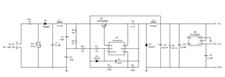
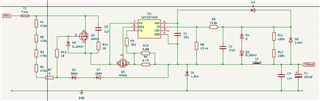
I struggled to find such high voltage input and low power converter application circuit but I came across the PMP11090 application circuit:

I'm wondering if it would be possible to modify it to make it widthstand 1kVdc entry instead of its actual 440Vac. To do so I would : 

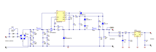
  • Remove the rectifier part since my input is already DC
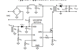
  • Remove the High voltage pin connection (since it can handle only 700V max input), I would create a start up circuit using a high value resistor connecting the 1000V to VDD as in ucc28700 application circuit (Rstr) : 
  • Use higher voltage break out mosfet, diodes and an inductor suited for the current spike

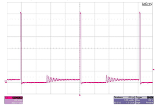
I think that by doing these modifications the component should be able to widthstand the 1kV entry but I would appreciate to have second opinions on this. One thing I'm afraid of is the Ton time on the mosfet on the test report of pmp11090, they provide the diode voltage at 440Vac (622Vdc equivalent) and it seems that Ton is about 500ns and it would be even shorter if using 1000Vdc input.

If you have any idea of circuit more suited for my goal, don't hesitate to tell me! 

Thanks a lot!

  • Hi Mathis,

    UCC28700 PSR flyback controller has a minimum on time requirement due to leading edge blanking time. UCC28700 buck from 1000V to 24V is not doable.

    Alternatively, I think a better option is to use a BJT Flyback like PMP10397. You can design a transformer to allow a larger on time. Also, you can have output voltage regulated to 4V or so and add an LDO after that to improve power consumption.

    Regards,

    Sheng-Yang Yu

  • Hi, thanks a lot for your clear answer.

    I don't know if you have the answer to this but do you think some other UCC28xxx controller could achieve such a conversion ratio? I saw on the PMP7668 that the UCC28722 is able to achieve 500Vac (or 700VDC) to 10VDC which is a bigger ratio than what I would require. The only problem is that UCC2872x are made for BJT buck and I need to use mosfet in my design.

    If anyone knows about a PWM controller that could do this while using a mosfet please let me know.

    Thanks again for your answer!

  • Mathis,

    PSR Flyback controllers we have all come with leading edge blanking feature. For example, UCC2872x leading edge blanking time is 355nS. Therefore, you will need to ensure the converter minimum on time is always greater than 355nS. Let's say 400nS.

    Consider a 1000V to 10V Buck converter with 20kHz switching frequency operates at CCM, on time will be 50uS x 1% = 500nS. As this is high voltage buck, you will likely operate under DCM, which mean duty cycle & on time will be even smaller. And potentially you will violate the minimum on time limitation.

    I went through 1000V to 10V Buck converter design using UCC28722 and notice that we only able to get ~250nS on time with the PSR control law...

    On other option is to use general PWM controller without build in leading edge blanking window like UCC28C5x.

    A high voltage buck with general PWM controller design example is shown below:

    https://www.ti.com/tool/PMP10833


  • Thanks again for your answer! I think I see it more clearly now.

    I recently came across your PMP11302 design where you use zener diodes and nmos to make a voltage drop to lower the input voltage of the ucc28881 and it seems like a brillant idea that could work for my requirement.

    I wonder if it would be possible to use this kind of system as an entry for the pmp11090 circuit. My intuition is that it would work since the rest of the circuit would see 500Vdc as entry (or a bit more) and this design can work up to 440Vac or 565Vdc. Otherwise, I can simply reuse entirely PMP11302's design but I'm afraid that the UCC28881DR will get too hot since in the application report it is already at more than 110°C at 914Vdc input.

    Could you confirm me that using a circuit similar to the one in pmp11302 as an entry stage for pmp11090 would work?

    Thanks again.

  • Here is the design I thought about, it's a mix between PMP11302 and pmp11090. The PMP11302 input regulates the voltage to around 500VDC and the pmp11090 allows conversion without overheating the controller since the mosfet is external and can be easily cooled.

    Do you think this would be viable?

    (just for the precision, the output voltage goal would be 24V, I would then convert the 24V into 3.3V using a similar circuit as in pmp11090, so I guess the on time shouldn't be too small even at low load since it works in the PMP11302)

  • Mathis,

    UCC28710 can work with cascode structure like PMP11090. However, the inductor and current sensing resistance in your design doesn't meet the UCC287xx PSR controller control law. It won't work. Can you send me your email? I can send you the design procedure I used for UCC287xx Buck.

    Regards,

    Sheng-Yang Yu