This thread has been locked.

If you have a related question, please click the "Ask a related question" button in the top right corner. The newly created question will be automatically linked to this question.

TIDA-010054: PLECS file

Part Number: TIDA-010054

Hi Team,

Our customer has some clarifications about the PLECS file in the TIDA-010054 reference design. According to our customer,

I don't fully understand the control blocks in the plecs simulation There are two control method Single phase shift and dual phase shift. My question is how they use the voltage signal difference to change the duty cycle of the switches?

This is the control block of the DPS(Dual Phase Shift) I wonder how to generate alphaP and alphaS

To elaborate:

1. How to generate alphaP and alphaS. What is the meaning of alphaP and alphaS? What is the internal phase shift angle and what is the external phase shift angle in this simulation as it is a DPS control implementation? And how to use the voltage reference signal to control the duty cycle of the switches.

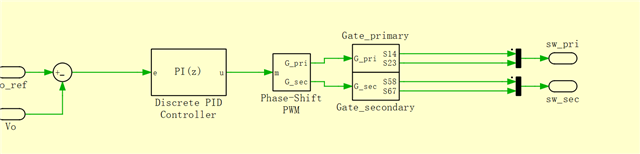
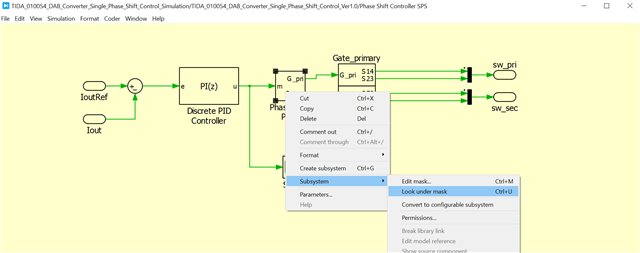
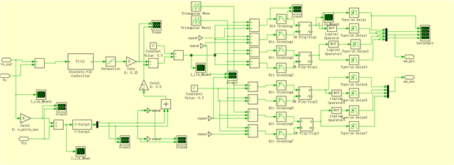
2. In this project. There's another file called SPS(single phase shift modulation). I also have a question about this PLECS simulation file. How to use the Discrete PID controller signal to generate the switch control signal? How to build the phase shift PWM?(This block is masked)

Regards,

Danilo

  • Hi Danilo,

    Thanks for reaching out.

    1 .AlphaP and alphaS are the secondary phase shifts. AlphaP is the phase shift between the two half-bridges on primary side and alphaS is the phase-shift between the two half-bridges on the secondary side. Both of them are caculated in the C-script block
    The phase shift between primary and secondary side is controlled by the PI-Control block. 

    2. For the single phase shift control file, the PWMs are generated inside the Phase-Shift PWM block. You can open these subsystems and have a look how if is done.

    Bets regards,

    Andreas

  • Hi Andreas,

    Thank you for your response. Please see the feedback of our customer below.

    Could you please help me solve these problems?

    I wonder how do they calculate the AplhaP and AlphaS by the C-script block? What are the theoretical equations or formulas to calculate the AlphaP and AlphaS? Besides, it is a Dual Phase Shift control block, which means it has two degrees of freedom, D1 and D2. But in the simulation, there seems to be 3 degrees, AlphaP, AlphaS and phase shift between primary side and secondary side. What is the relationship between AlphaP, AlphaS and the controller output?

    For the single phase shift control file, the Phase-Shift PWM block is masked which means I cannot open the subsystems. (The subsystem is hidden.)

    Regards,

    Danilo

  • Hi Danilo,

    The phase shifts alphaP and alphaS are calculated according to a scheme in the following paper:

    A. K. Jain and R. Ayyanar, "Pwm control of dual active bridge: Comprehensive analysis and experimental verification," in IEEE Transactions on Power Electronics, vol. 26, no. 4, pp. 1215-1227, April 2011, doi: 10.1109/TPEL.2010.2070519.

    There is either a additional phase shift on primary or secondary side, depending on input to output voltage ratio.

    You can open a subsystem with right-click and go subsystem -> look under mask.


    Best regards,

    Andreas