This thread has been locked.

If you have a related question, please click the "Ask a related question" button in the top right corner. The newly created question will be automatically linked to this question.

TLV8812 or LMP223x

Other Parts Discussed in Thread: TLV8812, TLV9062

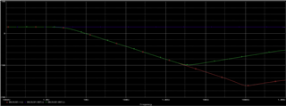
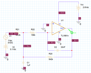
I am simulating a Sallen Key low pass filter with the -3dB at 3Hz. I noticed that results varied with the Vcc and that the results didn't follow expected function. I am getting a rebound in the amplitude response after about 100Hz (TLV8812). I simulated with an ideal op amp and got the results I expected. (no rebound) I then tried a higher bandwidth op amp (LMP223) and saw a similar rebound but after 1kHz. Why the rebound? I also noticed that the inputs to the 2nd stage op amp were not equal. See the schematic and response below.
  • Kenneth,

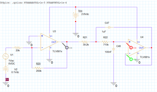
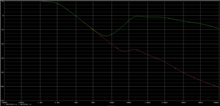
    You are on the right track regarding bandwidth.  The reason for the poor stop-band attenuation is related to the gain bandwidth of the amplifier (see attached PDF).  However, you can use a topology like multiple feedback (MFB) and the dependence on bandwidth is improved.  Also, it is recommended for low distortion to use C0G capacitors.  These type of capacitors are typically limited to 100nF.  So I adjusted the circuit with 100nF max capacitors.  Also, since these are low power amplifiers you should really use larger resistors.  Think of the capacitors as shorts at high frequencies and consider the output loading.   The attachment show the simulation results.  One issue with the MFB topology is that it is inverting.  Since your circuit is single supply, the output of the first stage will try to make the second stage go negative.  For example if the first stage is output voltage is +1V the second stage will try to go to -1V.  To fix this issue I used a psudo-ground of 2.5V.  In this configuration a 0V input will output 5V and a 5V input will output 0V (see transfer function in the document).  The last slide compares the SK to MFB.  You can see substantial improvement with MFB.  If you don't want to use MFB, you will have to substantially increase GBW.  I hope this is helpful to you.

    mfb vs sk tlv.pptx

    Best regards, Art

  • Art,

    Thank you for your efforts. One of the stipulations I needed to add was that I only have a negative voltage input and the op amps have to be single supply. I am also very limited to the power supply. My Vcc has to be 2.8V and the Iq of the op amp must be on the order of less than 10uA. So the first stage not only gave me the amplification of 10 but inverted the input from negative to positive. That means the filter must be non-inverting. I am not sure I can use a MF low pass filter since I think they are all inverting. Any quick response?

       --ken

  • I believe GBW has much to do with my issue both in performance and simulation. I tried the TLV9062 (10MHz) although it uses too much current and I still get the reversal of the filtering; starting to look like a bandwidth filter. Again, I used the sallen key filter but used 5V since I have seen some effect with the Vcc. Again, I can only use a Vcc of 2.8V and the input is always negative. I hope you can see the response.

    --ken

  • I got my best results using a single stage MF low pass.

  • Kenneth,

    I think you have a good solution and a good understanding of the issue.  You are correct that more gain bandwidth is required for the SK topology.  As long as you can use an MFB topology, you can use this  lower bandwidth device.  If you can afford to use extra power to get extra GBW you can use either topology.  You really don't have the option to use SK with a low GBW amp and get good results.  Based on your last response it seems like MFB may work for you but previous messages indicate that this is not the case.  In my example, I show an MFB topology that uses a pseudo-ground.  That is it has a supply equal to 1/2Vcc that allows the single supply configuration to look more like a dual supply configuration (Vcc,  pseudo-ground = Vcc/2, GND = Negative supply).  You can do the same thing with a 2.8V supply, but you will need to generate that voltage some how.  One possible way is to buffer a voltage divider.

    In any case, I am unsure if you are satisfied with your MFB solution.  Let me know if your last solution works or if you need further assistance.

    Art

  • Art,

    Thank you for your help. I think I know what I am going to do now. I am still puzzled why the spice simulation does not show the non-inverting and inverting inputs of SK model to have the same voltage. I am confident enough, however, to move forward.