Other Parts Discussed in Thread: TIDM-02008
Hi Team,
There're some issues from the customer need your help:
Are there any file to explain Current Loop, and Voltage Loop Algorithms?
1.The code to calculate the current loop code is as follows, how to understand it?
TTPLPFC_gi_out = GI_RUN(&TTPLPFC_gi,TTPLPFC_ac_cur_sensed_pu,TTPLPFC_ac_cur_ref_inst_pu);
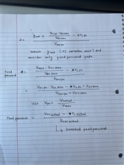
2. The output feed-forward code is as follows, how to understand it?
TTPLPFC_dutyPU = ( TTPLPFC_gi_out + (TTPLPFC_ac_vol_sensed_pu *
(float32_t)TTPLPFC_VAC_MAX_SENSE_VOLT /
(float32_t)TTPLPFC_VDCBUS_MAX_SENSE_VOLT)
- TTPLPFC_inductor_voltage_drop_feedforward )
/ (TTPLPFC_vBus_sensed_pu);
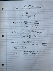
3. The feed-forward code for calculating the inductor voltage drop is as follows, how to understand it?
TTPLPFC_inductor_voltage_drop_feedforward = -(float32_t)1.0 *
(TTPLPFC_ac_cur_ref_inst_pu -
TTPLPFC_ac_cur_ref_inst_prev_pu) *
((float32_t)TTPLPFC_PFC_INDUCTOR_VALUE *
TTPLPFC_CONTROL_ISR_FREQUENCY *
TTPLPFC_IL_MAX_SENSE_AMPS /
TTPLPFC_VDCBUS_MAX_SENSE_VOLT);
TTPLPFC_ac_cur_ref_inst_prev_pu = TTPLPFC_ac_cur_ref_inst_pu;
4. The meaning of this part of the code
if(fabsf(TTPLPFC_vBusRef_pu - TTPLPFC_vBusRefSlewed_pu) > 0.0001f)
{
if(TTPLPFC_vBusRef_pu > TTPLPFC_vBusRefSlewed_pu)
{
TTPLPFC_vBusRefSlewed_pu = TTPLPFC_vBusRefSlewed_pu + 0.0001f;
}
else
{
TTPLPFC_vBusRefSlewed_pu = TTPLPFC_vBusRefSlewed_pu - 0.0001f;
}
}
else
{
TTPLPFC_vBusRefSlewed_pu = TTPLPFC_vBusRef_pu;
}
Could you help check this case?
Thanks & Regards,
Ben