This thread has been locked.

If you have a related question, please click the "Ask a related question" button in the top right corner. The newly created question will be automatically linked to this question.

TIDA-050060: Questions of design and setup system

Part Number: TIDA-050060

Hi team,

My customer have some questions here.

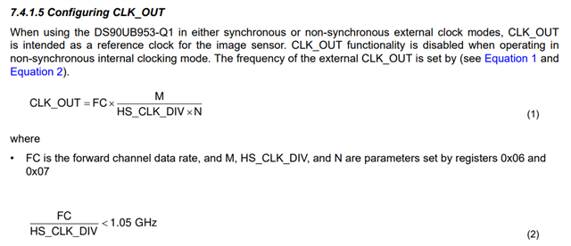
1.How can I setup the CLK_OUT to 24MHz?

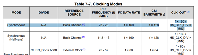
Regarding to datasheet Equation 1 and 2 below. FC is the forward channel data rate, and M, HS_CLK_DIV, and N are parameters set by registers 0x06 and 0x07. it mean I need to write registers 0x06 and 0x07 then I can achieve 24MHz CLK_OUT. is it correct?

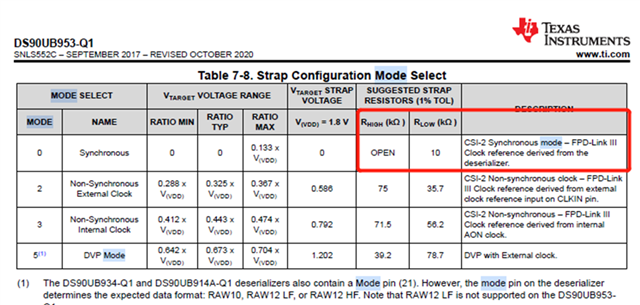
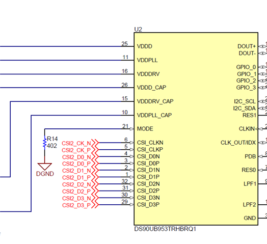
2.Select Mode 0 that Rhigh/Rlow = open/10kohms as first pic below datasheet. but TIDA-050060's schematic show that MODE Pin connect 402ohms to GND as 2nd pic below. i think 10kohms is correct. just would like to double check.

3.Since my customer is designing camera module following TIDA-050060. do we have any document can support customer to write the register of ser/des?

4.If we have setup the register of ser/des, PMIC and image sensor. what kind of thing we need to notice? or just connect image sensor to ser/des to display. Generally the image will be show on screen?  

BR,

Jimmy

  • Hello Jimmy,

    To answer some of your questions:

    1) This is correct. M, HS_CLK_DIV, and N are parameters set by registers 0x06 and 0x07, which you'd need to write to to set up.

    2) 10k Ohms is also correct.

    3) This would depend on which deserializer you're using and how you are interfacing with it. Are you using an onboard MSP microprocessor, or are you connecting directly to another processor somewhere else in the system?

    4) This also depends on which processor you are sending the deserialized data to. Could you provide me with additional details on which automotive processor they intend to use?

  • Hi Taylor,

    the camera signal path is: Image sensor --> MIPI interface --> 953 --> 954 --> MIPI --> to Nuvoton processor. 

    BR,

    Jimmy

  • Hello Jimmy,

    Thank you for the clarification. To answer your questions fully:

    1) This is correct. M, HS_CLK_DIV, and N are parameters set by registers 0x06 and 0x07, which you'd need to write to to set up.

    2) 10k Ohms is also correct.

    3) In this case you'd control and program the SerDes registers via I2C communications from the Nuvoton processor to the deserializer. The 954 deserializer can then read/write to the 953 serializer via I2C. For better understanding of this process, please see this design guide which focuses on how to interface a 954 deserializer with a 953 serializer. The I2C section begins on page 10.
    https://www.ti.com/lit/an/snla267a/snla267a.pdf?ts=1685971567428&ref_url=https%253A%252F%252Fwww.google.com%252F

    4) I'm not familiar with Nuvoton automotive processors, but if it runs on Linux then FPD-Link III drivers should be present and available for configuration. Beyond that you would need to configure the image sensor, but I believe you said you've already done that. In this case, the only thing to do is make sure the SoC is configured for real time video output, which would likely be a question for Nuvoton.