


Part Number: TIDA-01606
Hi TI's team,
Hope you have a nice day.
I meet some questions when I study the demo code. The details can refer the following description. I am looking forward for your reply. Appreciate your help.
Question 1: the sign of the decouplling network.
As we all know, the sign of the decoupling network is different because of there are four different types transformation matrixs. Please refer the following info(Four different transformation matrixs and two types decoupling networks).
a) Four types transformation matrixs.

b) two types decoupling networks.

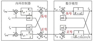
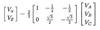
After studied, I believe that the first type transform and equal magnitude transformation is used in your demo code, which is shown as bellow.


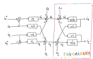
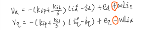
After we calculate the mathematical model, the dq-decoupling based current controller and it's mathematical expressions are shown as following.

But in your demo code, the sign of the decoupling network is contrary to us.
1. Decoupling network in demo code.
Code implementation
TINV_vdInv_pu = (TINV_gi_id_out +
(TINV_vGrid_dq0_pos.d *
(TINV_VGRID_MAX_SENSE_VOLTS / TINV_VBUS_MAX_SENSE_VOLTS)) -
(TINV_iInv_dq0_pos.q * TINV_DECOUPLING_CONST * TINV_AC_FREQ_HZ ));
TINV_vqInv_pu = (TINV_gi_iq_out +
(TINV_vGrid_dq0_pos.q *
(TINV_VGRID_MAX_SENSE_VOLTS / TINV_VBUS_MAX_SENSE_VOLTS)) +
(TINV_iInv_dq0_pos.d * TINV_DECOUPLING_CONST * TINV_AC_FREQ_HZ));
Simplify expression
vd=+pi(s)*(id_ref-id_feedback)+ed-wL*iq
vq=+pi(s)*(iq_ref-iq_feedback)+ed+wL*iq
2. Mathematical expressions.
Question 2: The sign about the output PI controller.
As described in Question 1, the sign of the PI controller is negative, but in your demo code, the sign is positive. So how about the reason?
vd=+pi(s)*(id_ref-id_feedback)+ed-wL*iq
vq=+pi(s)*(iq_ref-iq_feedback)+ed+wL*iq

Question 3: The detail modeling method about the dc-link voltage feedforward control.
DC-LINK voltage feedforward control is added in your newest code, could you please share some related modeling documents for us? And if it is possible, could you please share some comparison results with and without dc-link voltage feedforward control.
Question 4: Inverter mode and rectifier mode.
In demo code, TINV_idRef_pu = -1.0f * TINV_gv_vBus_out for PFC mode, TINV_idRef_pu = 1.0f * TINV_gv_vBus_out for inverter mode.
But in my opinion, d-axis represents the current magnitude (active component), while q-axis represents the phase angle between the converter's current and the grid side current (reactive component). So I think both for PFC mode and inverter mode, TINV_idRef_pu needs to be kept the same. We need to change the TINV_iqRef_pu based on the PFC mode and inverter mode, for example
TINV_iqRef_pu =0(PFC mode)
TINV_iqRef_pu =pi(inverter mode)
