


Other Parts Discussed in Thread: MSP-FET
Hi there,
It is great that the 10-pin debugger connector is added in LP-XDS110ET and recent XDS110-related LaunchPad(s). This is useful to debug custom boards. But there isn't UART channel in the 10-pin connector. I noticed pin-3, pin-5 and pin-7 are not used. They are grounded so far. It would be great to connect pin-3 to UART.RXD (i.e. TXD of DUT), pin-5 to UART.TXD (i.e. RXD of DUT) and pin-7 to TDIS/TEST.
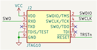
I have designed an adaptor to convert the 20-pin connector of XDS110 to a 10-pin connector. I also designed an adaptor to convert the 14-pin connector of MSP-FET Flash Emulation Tool to the same 10-pin connector. TEST (pin-7) is used by MSP-FET. TDIS (pin-7) is used by previous TI JTAG debuggers. The following picture shows the pinout used in my recent MSPM0 project. Note that the SWO signal is connected to MSPM0.TXD0. MSPM0 doesn't support SWO, I use UART0.TXD to emulate the SWO functionality.
In summary, in addition to the UART channel, this pinout definition will be compatible between 2-pin SWD, 2-pin JTAG, 4-pin JTAG, MSP-FET JTAG and SBW.
I have been using the adaptor for many years. It works great. Nowadays the PCB size of IoT devices are usually too small to use the original 20-pin connector. The 10-pin 1.27mm pitch pin header is good for most small PCBs. Hope that TI can consider this pinout definition in future XDS110 debugger and related LaunchPad.
Robert.
