Hi there,
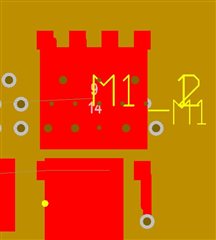
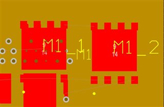
Just used webench to design a DCDC supply and two of the components (FET's) are shown as 'Quantity 2' on the schematic. All good, but unlike capacitors, I was unsure how to connect them up,. On downloading the PCB layout for Altium, the components in question are shown directly on top of one another. M1_1 and M2_1 occupy the same space (ditto with M2_1 and M2_2). Any idea how to solve this?
In images I have removed polygons and reset error markers. Second picture shows M1_2 moved off M1_1 to the right.