This thread has been locked.

If you have a related question, please click the "Ask a related question" button in the top right corner. The newly created question will be automatically linked to this question.

ULC1001-DRV290XEVM: Questions about the ULC system

Guru 12155 points
Part Number: ULC1001-DRV290XEVM
Other Parts Discussed in Thread: ULC1001, DRV2901

Hi, 

Q1.
I have tried many times to download ULC1001_GUI_v2p3p6.zip, but it always fails. Is it possible to send the zip file directly to me?

Q2.
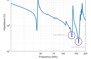
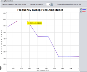
Am I correct in understanding that the role of IV sensing is used for temperature estimation and mass detection?
Is the temperature estimated by measuring the change in impedance of the piezo in terms of current value? The algorithm for mass detection is not clear.

Q3.
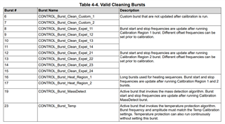
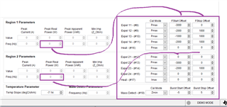
Why are there two different frequency settings for cleaning bursts: region 1 and region 2?

Q4.
Can you tell me why there are two heating bursts in the Deice Cleaning Profile within the ULC1001 datasheet.
Looking at the default settings in the GUI, it appears that 'CONTROL_BURST_Heat_Region_1' is set to one BURST.
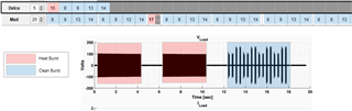
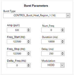
Q5.

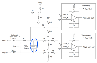
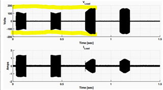
Are [mV] and [A] the correct units for the voltage and current values in this diagram?

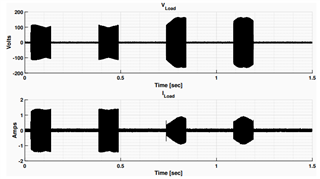
Also which specific areas are VLOAD and ILOAD measuring in the diagram below?
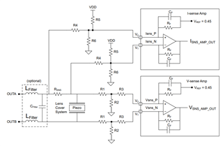
Q6.
Is there any information on failures and reliability regarding the ULC? I am wondering, for example, how much durability testing a Customer should do before a mass production shipment is made.

Thanks,

Conor

  • Hi Conor,

    Thanks for reaching out. 

    Q1: Have you tried to download it recently? We had an issue with the GUI download link that was recently resolved. If this still does not work please let me know and we will figure out another solution. Sorry for any inconvenience!

    Q2: All of the active bursts activate the IV sense path (bursts 0-5 and 19-23) which includes but is not limited to the temperature and mass detection algorithms. Specifically, bursts 1 and 5 are the calibration bursts for mass and temperature detection that will collect a reference measurement. When the cleaning bursts 19 or 23 are used, which are the mass detect and temp cleaning bursts, they will measure again but do a comparison to the measurement taken at calibration. If the measurement change is over a certain threshold, then it will react accordingly (heat up, cool down, do a water cleaning sequence, etc.).

    Q3: When you drive at a frequency, there are certain parts of the lens that do not move / vibrate (dead spots). If you try to clean the lens at one frequency, you will likely not be able to expel the water on these dead spots which will leave rings of water on the lens. When you drive at a different frequency, you still have dead spots, but they are different than the first frequency. So when you drive two frequencies (region 1 and region 2) you are vibrating the entire lens. Below is a screen shot of the LCS simulation (radius cross section) at two different frequencies with the dead spots circled. As you can see, where one frequency has a dead spot, the other will vibrate.

    Q4: In the data sheet the two heating bursts run for a total of 10 seconds, each burst being 4 seconds with a 2 second delay in between. The GUI default is just one burst that's duration is a total of 10 seconds so the two operations are not much different, but this is definitely an update we need to make in the datasheet. Thank you for bringing this to our attention!

    Q5: The units for the plots are volts and amps. This is the measured output from the EVM during a water cleaning cycle which is just measured across the load / LCS which I circled in blue. 

    Q6: TI's chips are thoroughly tested to the datasheet parameters, but the Lens Cover System that we released with our EVM is a prototype intended only to demonstrate the technology. The mechanical system will need to be owned by the customer.

    Hope this helps!

    Regards,
    Sydney Northcutt 

  • Hi Sydney Northcutt,

    Thanks for the detailed explanations. The content was understood, except for Q5.

    Q5: The units for the plots are volts and amps. This is the measured output from the EVM during a water cleaning cycle which is just measured across the load / LCS which I circled in blue. 

    Perhaps I do not have a good picture of what happens when a piezo is excited. My image is as follows.

    The ULC1001 is a PWM modulator. The DRV2901 is a gate driver, so my understanding is that it has the function of amplifying the PWM output from the ULC1001. The PWM is amplified up to 48 V by the DRV2901.
    The PWM signal output from the DRV2901 becomes a smooth sine wave via an LC filter and is applied to the piezo.

    Can you please tell me where I am wrong in my above understanding? It is not clear why a voltage of ±150 V is applied to both ends of the piezo.

    Also I describe additional questions in Q6.

    Q6.
    How does the user need to change the Burst Enumeration? For example, WaterBURST has a series of sequences (8 -> 9 -> 13 -> 14). The understanding is that these should not be changed in a series of patterns.
    Related to the above order, I do not understand the difference between BURST8~11 and BURST12~15. I also do not understand the difference between BURST16 and BURST17 as well.

    If the user proceeds with development using the GUI, what steps need to be taken and which parameters need to be changed? It would be easier to understand if there is a procedure manual or WORKSHOP document on how the user should set up the GUI.

    Thanks,

    Conor

  • Hi Conor,

    Q5: Your understanding is correct, but the LC filter brings the magnitude of the impedance lower, which combined with the equivalent Q of the LC filter will lead to voltage gain. This is commonly referred to as a ringing system.

    Q6: Burst 8-11 and 16 are updated from the region 1 parameters from calibration. Bursts 12-15 and 17 are updated from the region 2 parameters from calibration. They are updated by the Fstart and Fstop Offsets that you can see and customize on the right side of the GUI. You can also change the number and order of the bursts in the GUI. It does not have to stay in default settings. 


    As for development with the GUI, the detailed information for each section and explanation of the process can be found in the User Guide (sections 4 and 5). If using a lens cover separate than the TI LCS prototype, the first step would be to take an impendence sweep of your lens cover so you can update the frequency ranges accordingly. The default ranges are optimized the the TI LCS.

    Regards,
    Sydney Northcutt

  • Hi Sydney Northcutt,

    Thanks to your answers I have a general understanding, let me make some additional clarifications on Q5 and Q6.

    Q5.
    LC filters are amplified to -200V~200V using the effect of amplifying the peak voltage at certain frequency components. From checking the datasheet, the LC filter is optional, so there may be cases where it is not necessary to place it. Am I correct in understanding that the LC filter is placed when a voltage gain is desired? Or is there a different criterion?
    You can also select a piezo and determine the approximate voltage by calculating the voltage gain from the Q-value of the LC filter. The value of the external resistor is then determined. Is it correct that this order determines the voltage value fed back to the ULC1001?

    Q6.
    The Clean Burst oscillates at a combination of different frequencies in Regions 1 and 2. We understood that the reason for this was to eliminate dead spots on the lens. We also understand that the lens oscillates around the resonance frequency.
    By the way, I think that these Region 1/2 frequencies are values near the resonance frequency, but I wonder how they are determined. Are the Region 1/2 frequencies the primary and secondary resonance frequencies? I am not very familiar with piezos, so I don't really understand if there are always first and second order resonant frequencies.

    Thanks,

    Conor

  • Hi Conor,

    Q5: Yes, the LC filter is placed when voltage gain is needed. Also, it will mitigate the ringing that would occur driving a pure square wave into the capacitive load which reduces EMI. For the second part of Q5 question, can you clarify what resistor you are talking about? Are you referring to the IV sense? 

    Q6: Yes, the region 1 and 2 frequency ranges declared in their respective bursts are around the resonance frequencies. These are determined be taking an impedance sweep across the LCS. We do this using an impedance analyzer and sweep from 20kHz to 200kHz. 

    Regards,
    Sydney Northcutt

  • Hi Sydney,

    can you clarify what resistor you are talking about? Are you referring to the IV sense? 

    Q5 : Yes, I was referring to IV sense resistors.

    Yes, the region 1 and 2 frequency ranges declared in their respective bursts are around the resonance frequencies.

    Q6 : For example, in the default settings of the GUI, Region 1 shows around 120 KHz and Region 2 around 140 KHz. Am I correct in understanding that in this case the resonant frequency is around 130 kHz?In other words, is there a resonant frequency between Region1~Region2? Also when performing a frequency sweep, the resonant frequency will be the highest voltage value by IV sensing, correct?

    Conor

  • Hello,

    Q5: You can find information on how to calculate the IV sense resistive divider network in the ULC1001 datasheet (section 8.5.2 Voltage and Current Sense Circuitry). These IV sense pins are sensitive, so they need a voltage divider network to reduce the voltage. 

    Q6: No, these are two separate resonance frequencies. In the impedance response of the LCS, which is taken on an impedance analyzer, you can see the resonance peaks and note the frequencies, but this is just for the LCS. The addition of the LC filter will shift this frequency slightly left and other factors such as temperature could slightly change it as well. Calibration bursts 2 and 3 are set with fstart and fstop values which are ranges around a frequency noted from the LCS impedance sweep. Burst 2 updates the region 1 parameters, and burst 3 updates the region 2 parameters. When calibration is run, burst 2 will do various measurements using IV sense and update the region 1 parameters. Similarly, burst 3 will do various measurements using IV sense and update the region 2 parameters. Note that these measurements are only done within the bursts declared frequency range. Below is an example impedance sweep for the LCS.

    Regards,
    Sydney Northcutt

  • Hi Sydney Northcutt,

    Your answers have given me a very good understanding of ULCs.

    Q5.
    I understand that IV sensing is mainly used for temperature and substance detection by detecting changes in impedance. Incidentally, impedance also changes with changes in temperature. The impedance also changes in the same way when a substance adheres to the lens. I feel that the DSP side cannot judge these differences from the point of view of impedance decrease, but how do you judge temperature change and substance adhesion?

    Q6.
    I understand that I can check the resonance frequency using an impedance analyser. When actually using the GUI for development, the resonant frequency can be set automatically for Range 1 and Range 2. So checking the frequency with an impedance analyser is optional in the ULC development flow, is it not? Also, in the USS of the MSP430 I can view the sweep measurement graphically, is there such a function in the ULC?

    Thanks,

    Conor

  • Hi Conor,

    Q5: A temperature change and mass on the lens are detected / measured a little bit differently. For temperature, we are looking for a change of impedance at one frequency. For mass detection, we are looking for a frequency shift of the resonance peak. Both of these have certain thresholds in the GUI, where if the change is over the declared threshold, then it will respond accordingly. 

    Q6: "When actually using the GUI for development, the resonant frequency can be set automatically for Range 1 and Range 2" - No 

    In the GUI, the default frequency ranges for burst 2 and 3, that update the region 1 and 2 parameters, are optimized for the LCS by taking an impedance sweep externally. If you are creating a new lens cover system, it is recommended to take an impedance sweep to then update the burst 2 and 3 frequency ranges as they will be different from the TI LCS. The ULC device can not take a sweep from 20kHz to 200kHz and find the true resonance peaks, which is why we use an impedance analyzer. Using that information, we then provide the ULC device with smaller frequency ranges around the peaks. You also want to do this external sweep to properly set up the temperature detection for new LCS, as these defaults in the GUI are also optimized for the TI LCS.

    Regards,
    Sydney Northcutt