This thread has been locked.

If you have a related question, please click the "Ask a related question" button in the top right corner. The newly created question will be automatically linked to this question.

TIDA-01527: After manually modifying the excitation frequency in the code to 10k, the EXC waveform is distorted. How to solve it?

Part Number: TIDA-01527

Hi Team,

There's an issue from the customer need your help:

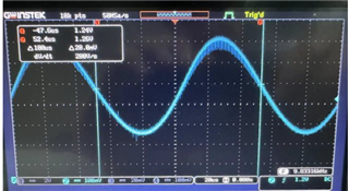
Hello, when I use this reference design, in order to make it more suitable for my resolver parameters, I try to modify the excitation frequency from 5kHz to 10kHz (the specific operation is to change EXC_STEPS_PER_PERIOD 64 /* 2^6 - > 6- bit resolution per EXC period */The 64 in this line of function is changed to 32), but the OEXC excitation waveform displayed on the test terminal is slightly distorted (the graph is slightly offset). Is it my operation that is wrong or something else? reason? I hope the engineer will reply as soon as possible, thank you very much!


Thanks & Regards,

Ben

  • Hi Ben, I don't have the hardware available at the moment. I believe you need to play with the cut-off frequency of the MFB filter. Please take a snapshot from of the EXC+ and EXC- signals with the reference to ground. Use the in-built function in the oscilloscope to do the delta (Math Ch1-Ch2). It provides clearer picture.

    For the filter cut-off frequency change, use http://sim.okawa-denshi.jp/en/OPtazyuLowkeisan.htm . This online tool helps you to quickly evaluate new values of C3 and C4. Set the frequency to ~20 kHz.

    Best regards, Jiri