Other Parts Discussed in Thread: TPS54260
How to solve this problem?
This thread has been locked.
If you have a related question, please click the "Ask a related question" button in the top right corner. The newly created question will be automatically linked to this question.
Hi YX,
I downloaded the files from the product folder
https://www.ti.com/product/TPS54260#design-tools-simulation
and ran the simulation without any errors.
There's both an AVERAGE, and an AVERAGE Package. Please use the package as it has everything you need.
Here's my version of PSpice for TI:
I used AVERAGE Package!
And software version is the same,installed last night.
Is there some other reason?
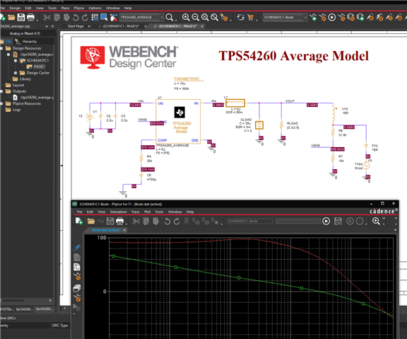
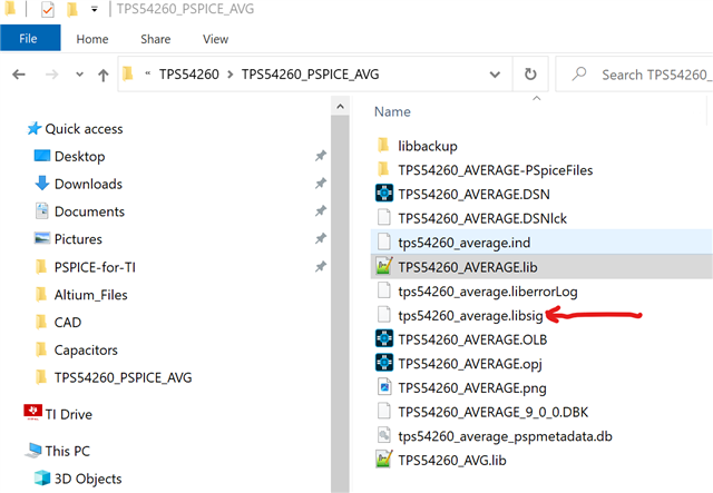
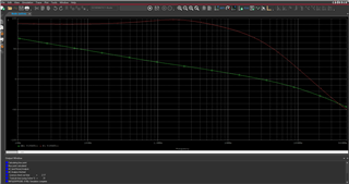
I had used the .lib file from the Average Model and the rest of the files from the Average Package. I replaced the .lib with the Average Package .lib and reran without a problem.
Did you make any changes to the .lib file?
Can you try downloading the .lib file again and see if it'll run?
I'll check to see if the location has anything to do with this.
David
My collegue was able to reproduce your error and we've tracked down what's causing it.
Please put this file into the folder with the .lib file. That should resolve your problem.
Davidhttps://e2e.ti.com/cfs-file/__key/communityserver-discussions-components-files/234/tps54260_5F00_average.libsig
Still Error
log as below:
**** 09/07/23 23:43:47 ******* PSpice 17.4.0 (Nov 2018) ******* ID# 0 ********
** Profile: "SCHEMATIC1-Bode" [ F:\2023 Learn\Pspice\TPS54260\source file\TPS54260_PSPICE_AVG\tps54260_average-pspicefiles\schemati
**** CIRCUIT DESCRIPTION
******************************************************************************
** Creating circuit file "Bode.cir"
** WARNING: THIS AUTOMATICALLY GENERATED FILE MAY BE OVERWRITTEN BY SUBSEQUENT SIMULATIONS
*Libraries:
* Profile Libraries :
* Local Libraries :
.LIB "../../../tps54260_average.lib"
* From [PSPICE NETLIST] section of C:\cds_spb_home\cdssetup\OrCAD_PSpiceTIPSpice_Install\17.4.0\PSpice.ini file:
.lib "nom_pspti.lib"
.lib "nom.lib"
*Analysis directives:
.AC DEC 100 10 500000
.OPTIONS ADVCONV
.OPTIONS FILEMODELSEARCH
.INC "..\SCHEMATIC1.net"
**** INCLUDING SCHEMATIC1.net ****
* source TPS54260_AVERAGE
V_V1 VIN 0 12
R_R7 0 VSNS 10k TC=0,0
C_Cinj N14530432 N14530438 1E6 TC=0,0
X_L1 PH VOUT LDCR PARAMS: L={L} DCR=26m IC=0
V_V3 N14530432 0 DC 0Vdc AC 1Vac
R_RLOAD 0 VOUT {3.3/2.5} TC=0,0
R_R4 N14530420 N14530386 20k TC=0,0
R_R6 VSNS N14530438 31.6k TC=0,0
C_C6 0 N14530420 4700p TC=0,0
L_Linj VOUT N14530438 1E6
X_CLOAD VOUT 0 CESR PARAMS: C=35u ESR=3m X=2 IC=2
X_U1 VSNS PH N14530386 VIN 0 TPS54260_AVERAGE PARAMS: L={L} FS={FS}
C_C2 0 VIN 2.2u TC=0,0
C_C3 0 VIN 2.2u TC=0,0
.PARAM l=10u fs=300k
**** RESUMING Bode.cir ****
.END
WARNING(ORPSIM-15256): <X_L1.IC> not a subcircuit param
WARNING(ORPSIM-15256): <X_CLOAD.IC> not a subcircuit param
INFO(ORPSIM-16573): AC analysis does not support expression evaluation at each frequency. ABM devices with non-linear operations will be evaluated only at bias point.
**** 09/07/23 23:43:47 ******* PSpice 17.4.0 (Nov 2018) ******* ID# 0 ********
** Profile: "SCHEMATIC1-Bode" [ F:\2023 Learn\Pspice\TPS54260\source file\TPS54260_PSPICE_AVG\tps54260_average-pspicefiles\schemati
**** Diode MODEL PARAMETERS
******************************************************************************
X_U1.X_U1.Xdc.dclamp
IS 10.000000E-15
N .01
RS .1
X_U1.X_U1.Xd2.dclamp
IS 10.000000E-15
N .01
RS .1
ERROR(ORPSIM-16592): Detected an imported model containing transistors or diodes. For such models, PSpice for TI supports a minimum of one and maximum of three traces. No traces added for data collection. Add at least one trace and simulate again.
ABORTING SIMULATION
**** 09/07/23 23:43:47 ******* PSpice 17.4.0 (Nov 2018) ******* ID# 0 ********
** Profile: "SCHEMATIC1-Bode" [ F:\2023 Learn\Pspice\TPS54260\source file\TPS54260_PSPICE_AVG\tps54260_average-pspicefiles\schemati
**** JOB STATISTICS SUMMARY
******************************************************************************
Node counts:
Top level (NUNODS) = 8
External (NCNODS) = 29
Total (NUMNOD) = 33
Total device count (NUMEL) = 50
Capacitors (C) = 7
Diodes (D) = 4
VCVS (E) = 10
VCCS (G) = 7
Inductors (L) = 2
Resistors (R) = 11
Voltage Sources (V) = 7
Number of subcircuits (X) = 7
Matrix statistics:
Matrix size (NSTOP) = 52
Initial no. elements (NTTAR) = 128
No. elements w/ fillin (NTTBR) = 128
No. fillins (IFILL) = 0
No. overflows (NTTOV) = 0
No. LU operations (IOPS) = 0
Percent sparsity (PERSPA) = 95.266
Analysis statistics:
No. total time points (NUMTTP) = 0
No. rejected time points (NUMRTP) = 0
No. iterations (NUMNIT) = 0
Load Threads = 1
Runtime statistics: Seconds Iterations
Matrix load = 0.00
Matrix solution = 0.00 1
Readin = .33
General setup = 0.00
CMI setup = 0.00
Setup = 0.00
DC sweep = 0.00 0
Bias point = 0.00 0
AC and noise = 0.00 0
Total transient analysis = 0.00
Output = 0.00
Overhead = .03
License check-out time = .73
Total job time (using Solver 1) = .33
--------------- INFO(ORPROBE-3209): Simulation Profile: SCHEMATIC1-Bode ---------------
INFO(ORPROBE-3183): Simulation running...
** Profile: "SCHEMATIC1-Bode" [ F:\2023 Learn\Pspice\TPS54260\source file\TPS54260_PSPICE_AVG\tps54260_average-pspicefiles\schemati
Reading and checking circuit
WARNING(ORPSIM-15256): <X_L1.IC> not a subcircuit param
WARNING(ORPSIM-15256): <X_CLOAD.IC> not a subcircuit param
INFO(ORPSIM-16573): AC analysis does not support expression evaluation at each frequency. ABM devices with non-linear operations will be evaluated only at bias point.
Circuit read in and checked, no errors
ERROR(ORPSIM-16592): Detected an imported model containing transistors or diodes
Run aborted
License check-out time = .73
Total job time (using Solver 1) = .33
INFO(ORPROBE-3188): Simulation aborted
Can you show me your file folder for your sim? It should looke something like this:
Here's the .lib file that the .libsig corresponds to. JC has verified this.
I can simulate the result.Thanks.
But I can not see phase Y axis,how to configure?
Here's a link to instructions on Bode Plots in PSpice.
There is the option to add Y axis. Just go to Plot, Add Y Axis.
Can Pspice for TI simulate buck load Transient?
Is there a user guide for buck load Transient simulation?
Thanks!
Here are some handy articles that may help in general if not your specific question regarding how to simulation buck load Transient sim.
App note on Switching regulator fundamentals:
https://www.ti.com/lit/an/snva559c
List of buck regulator reference designs:
https://www.ti.com/reference-designs/index.html#search?famid=64,661,490
David