This thread has been locked.

If you have a related question, please click the "Ask a related question" button in the top right corner. The newly created question will be automatically linked to this question.

TIDA-010042: Is Q4 mounted the wrong way around?

Part Number: TIDA-010042

I was trying to understand the PNP floating voltage measurement, which I could not simulate... I don't understand how it works. But then, I realized that the body diode of Q4 prevents switching off the panel, because the current then just flows over the body diode back to the panel.

Is this a design error, or do I miss something?

Thanks, Edi

  • Hi Eduard,

    Q4 can help prevent current going into panel when battery voltage is higher than panel voltage (if so, the software will turn off Q4, then panel will be disconnected). If panel voltage is higher than the battery voltage, and other parameters are met (you can see the judge criteria from design guide), then software will turn Q4 on to reduce the conduction loss.

    The voltage measurement current can go through Q4's body-diode, then it will give a correct value. If the Q4 turns 180 degrees, then when Q4 is off, PV panel's voltage cannot be detected.

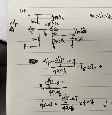
    The PNP voltage measurement works like this (in this TIDA design, actually a non-floating voltage measurement can work too (such as a simple resistor voltage divider)), you can simulate it in TINA:

    PV_voltage_sample.TSC

  • Hi Browden,

    thank you very much. Ah, and now I understand also why the 10V step down regulator also works with no sun light! It is feed back from the battery through the body diodes of Q6 and Q7!

    Ok, thank you a lot, I'll build it without the floating sensing circuit.