This thread has been locked.

If you have a related question, please click the "Ask a related question" button in the top right corner. The newly created question will be automatically linked to this question.

TIDA-01487: upgrading the design to 5Mbps

Part Number: TIDA-01487

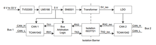
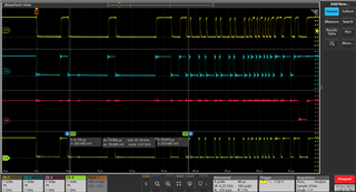
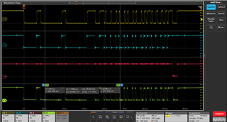
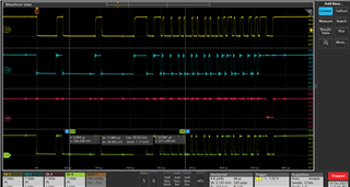
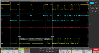
Hello, I would like to isolate CAN running 5Mbps. However I am not able to do that. I used faster Logic-Gates (74ACT line), faster CAN transceiver (up to 8Mbps), and lowered the delay of the delay line to 100ns. Everything works fine for 4Mbps but I can't achieve 5Mbps. Do you have any suggestions what may limit me to 4Mbps or in gerneral limit the transmission speed in this circuit?

kind regards Jonas

  • Hi Jonas,

    Thanks for your question. In parallel we are actually investigating how to increase the speed to 8Mbps which is an ongoing activity.

    To address your question. Refer to the diagram in the TI design: The limiting factor is the round trip delay of the resistive state from TX2 over the isolator device through the CAN transceiver (CAN side) and back over the isolator device to the RX2. This time should derive the maximum speed, and I think you need to get this as low as possible. Also the bus arbitration logic should open the gate within the time of the achievable baud rate.

    I think you would need to investigate/measure the timings of the circuit to see where it get stuck. 

    Can you let me know which CAN transceiver and isolator device you are using?

    Regards,

     Thomas

  • Hallo Thomas, in my current test setup I use the MCP2561 CAN transceiver and the SI8422AD-B-IS  because we had these parts laying around.
    kind regards Jonas

  • Hi Jonas,

    Thanks for providing the information.

    Obviously we cannot solve/work here with a non-TI device solution ;-)

    Our FAE will contact you to help you in getting TI samples. As I mentioned above, we look into a updated design on how to enable higher baud rates and this will most likely also achieve the CAN frequency you are looking into. I will share some further details once available with your via the FAE.

    Thanks and regards,

     Thomas

  • Hi Thomas,

    Is there a rough timeline for the new design?

    kind regards Jonas

  • Hi Jonas,

    For your current design, can you measure the delay logic circuit time. I think you need to confirm that this tine is between the delay time of  > 2 x ISO + CAN Transceiver and < 200ns (5Mpbs).

    Regarding the timeline. I will have some design ideas/conclusions by e/o next week.

    Regards,

     Thomas

  • Hi Thomas, my Delay line has a delay of 250ns rn. The strange thing is that 5Mbps works with some can messages and with others it  doesn't.

    For example:

    speed : 4Mbps 

    msg: 02 02 02 02

    direction: CAN1 → CAN0

    --- RX1
    --- TX1
    --- TX2
    --- RX2 

    speed: 5Mbps

    It can be seen that everything works like it should.

    But...

    speed : 4Mbps 

    msg: 21 21 21 21

    direction: CAN1 → CAN0

    --- RX1
    --- TX1
    --- TX2
    --- RX2 

    speed : 5Mbps 

    --- RX1
    --- TX1
    --- TX2
    --- RX2 

    No ACK for receiver. I assume that this has nothing to do with the delay line because as far as I understand it the delay line is only needed to block the RX Line. But the ACK doesn't get blocked it is not sent by the receiver.

    Any ideas/suggestions?

    If I understand your last comment right my delay line should be 

    Propagation delay Txd to Rxd + Propagation delay ISO * 2  > x > 200ns
    in my circuit this would be:
    120ns + 11ns * 2 > x > 200ns
    142ns > x > 200ns

    right?

    I testet it with 190ns before but with smaller delays then my current setup it stops working at all.

    kind regards, Jonas

  • Hi Jonas,

    Thank you for providing the scope plots.

    I do agree that the delay line has most likely no influence at 5 Mbps in the failing case. I also think that the receiver should send the ACK in case he did receive the signal well.

    So maybe this is the issue here. Somehow the data stream on CAN0 side is getting distorted so the the receiver does not understand the message and does not provide the ACK.

    Do you have any measurement instrument to see/sniff the message on the CAN0 side? Is there maybe some CAN bus termination resistor missing?

    I would suggest to look at the CAN side next, to identify why the CAN receiver does not sent the ACK. Because right now the CAN message should be 1:1 routed through the two CAN transceiver and the isolation without getting broken.

    Regards,

     Thomas