This thread has been locked.

If you have a related question, please click the "Ask a related question" button in the top right corner. The newly created question will be automatically linked to this question.

TIDA-010242: TIDA-010242

Part Number: TIDA-010242

Good Morning,

I am working through the apps note for the TIDA-010242 and checking the calculations with a view to modifying or creating a similar design for a slightly modified version of 1275D.

I am currently looking at the SOA calcs in para 2.2.6 and I would like to ask a little about the numbers that are in the apps note.

I follow the concept of calculating the stress square pulse and I get the same values shown. When I get the SOA calcs I believe that the design is extrapolating from the SOA chart from the manufacturer.

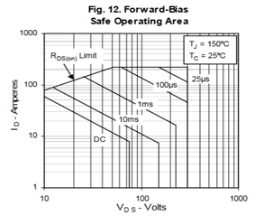
Would you be able to explain how the 1 second and 10ms currents were extrapolated at the 50V line? By eye I would choose slightly different values, but I wondered if you were calculating them somehow?

If I use the values given in the notes then I get the same current at the 218ms square pulse model time, and at this point I'm not able to understand the power or time that is mentioned in this sentence:

"Plugging in the numbers for the IXTT88N30P results in an SOA of 15.7 A, meaning that the IXTT88N30P can handle 439.6 W for 252 ms. Which indicates this is more than enough for a 120-W system at
25°C."

Could you detail how these figures are calculated? I'm wondering if they are based on projecting the SOA current of 15.7A on the 50V line for the time, but the figures seem too accurate for a visual estimation.

Thanks in advance!

  • I should clarify that my confusion is with 439.6W and 252ms

  • Ian,

    For your first question, yes, the values were visually extrapolated from the chart. This is always a judgment call from the designer, but conservative values should be used in cases like this.

    Regarding the 439.6W; this is just the product of the SOA current and the operating voltage of 28V. You can think of it as reversing the original operating point of the load, just using the FET SOA.

    The 252ms however, I believe is a typo by the original designer, and should read 218ms. I'll work with our team to get this fixed.

  • Hello Bart,

    Thank you for the clarification. Is there any particular reason that the power wasn't calculated using the 50V across the device during the transient event? That would be what I would have done initially as I was looking to see that the device was within its SOA during the surge, although calculating the power at this time seems a bit pointless unless we want to compare the energy with that of the surge itself.

    Could I extend my question a touch to ask about the thermal derating values that are used? It would be useful to know the actual theta and Rdson values that are used in the calculations that follow. In order to get a similar result to that in the apps note I find that I need to modify the Rdson value (listed as 49mR @25C) by more than I would expect from the normalised Rds vs junction temperature graph. Knowing the rational for selecting those values helps with the confidence that the thermal considerations have been made correctly when I come to do this myself.

    If this would be better as a separate question, please let me know and I will mark your initial respose as resolving my issue.