


Team,
Customer is testing TIDA-01606 PCB rev 6 using the TMDSCNCD28379D and latest Digital Power SDK 5.00.01.00.
I have made some measurements with LAB7 test mode and the results as below,
- We have started initially with 60VAC3 (Line to Neutral Voltage)and output DC voltage reference set to 500VDC.
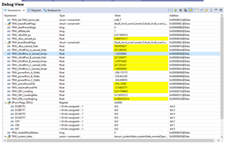
The voltage and current are in sync. But the iGridRms (~3A) currents displayed in CCS debug window and our measurement (6Arms) doesn’t match. There is almost a factor of 2.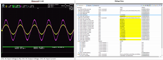
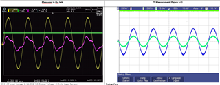
2. We slowly increased the AC input voltage to 230VAC3 (L-N) and Output DC Voltage to 700VDC and the output power to around 1.7kW (Comparable to tidue53i userguide, Figure 3-9). Check the pictures on the left measured at Stercom and on the right reference measurement from user guide.
All the tests were performed with default regulator parameters as in LAB7 exercise and Electronic Load from Delta Elektronika (15kW) was used for the tests.
From the schematic, the shunt resistors (R5, R41 & 47) used for iGridRms sensing are 2mohm type. Check if this was changed or any changes needed in code for AMC1306 (Delta-Sigma) scaling factor?
In addition, please let us know if the additional LEM current sensors (CASR-15-NP) U3, U4 and U5 are used for regulation or measurement?
Thanks in advance,
A.
