Because of the holidays, TI E2E™ design support forum responses will be delayed from Dec. 25 through Jan. 2. Thank you for your patience.

This thread has been locked.

If you have a related question, please click the "Ask a related question" button in the top right corner. The newly created question will be automatically linked to this question.

TIDA-01352: Max output current main rails

Part Number: TIDA-01352
Other Parts Discussed in Thread: LM5030

Hi,

I have built the reference bard design TIDA-01352 and I'm looking at the performances using an electronic load.

I cannot reach the performance given in the design guide TIDUCD8.PDF chapter 3.2.2.3.

+LV and -LV output currents are limited to ~1.2A at 50V.

+MID section support >2A at 50V.

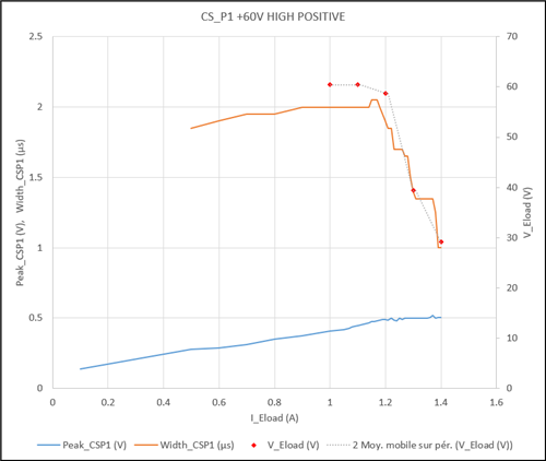
I have measured that CS_P1 current sense voltage reach 0.5V at ~1.2A at 50V. Above 1.2A the CS_P1 duty cycle decrease, like if the LM5030 enter a cycle-by-cycle regulation (as intended).


Components parts number, including inductors, has been bought according to the reference design BOM.

Did you get similar feedback about a limited output power capability of the reference design ? Does some component may affect this specification?

Best regards,

Nicolas.

  • Hello,

    Does anyone experienced this before ?

    Best regards,

    Nicolas.

  • Hello,

    Sorry for the delay.

    How many boards have you tested? It looks like your design is going into current limit due to some component changes.

    Do you have your schematic to share?

    Regards,

    Sanjay R. Pithadia

  • Hello,
    Thank you for your reply.

    We build the TIDA-01352 reference design from TI as it. No intended modification.
    Transformers bought to Wurth.

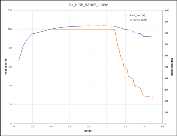
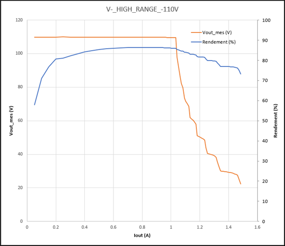
    Bellow, the measured I/V curves on one board. I have a second one that can be tested but components are from same orders.
    Input voltage at the primary transformer is 23.3V (+MID channel).

    Resistors on current sense circuits have desired values.

    Current sense circuit seems to limit current. Here the measurement on the signal on the main positive channel at +60V:

    Do you have advices for me to look around ?

    BR,

    Nicolas.

  • Hello, I don't see any reason if you have copied the TI schematic as is. Can you please share PDF of the schematic for review?

    Also, can you please test this issue on more boards?

  • Hello,
    I get the same behavior on the second board i have.

    I would like to clarify the current waveforms given as reference on the design guide TIDUCD8.PDF :
    Figures 53 & 54 : B-Mode -> clearly described in §3.2.1
    Figures 55 & 56 : Elastography -> clearly described in §3.2.1
    Figure 57 : Full Load -> means constant current ?
    Figures 62 & 63 : CW -> continuous pulses, similar to §3.2.1 with toff = 0 ?

    Could you please confirm that for each figure, current values given is charts represent the current during the pulses, and not the average current delivered by the PSU ?

    Using ELoad, I see that the positive main channel can output 2.5A pulses (square wave 250us @2A5, 250us 0A) as regulation stabilizes.

    /cfs-file/__key/communityserver-discussions-components-files/234/HIGH_5F00_POS_5F00_50V_5F00_2A_5F00_250us_5F00_500us.bmp

    Blue trace is the voltage accross 0.025Ohm located on the negative terminal (GND) of the Eload.

    Thank you very much for your support.

    Nicolas.

  • Hi, Nicolas

    nice to meet you here!

    "Figures 53 & 54 : B-Mode -> clearly described in §3.2.1
    Figures 55 & 56 : Elastography -> clearly described in §3.2.1
    Figure 57 : Full Load -> means constant current ?
    Figures 62 & 63 : CW -> continuous pulses, similar to §3.2.1 with toff = 0 ?"

    yes. you are right. during B-mode, since the load is a pulse and there is buffer capacitor in output, so the transient current can arrive 2.5A. but the continus current is ~1A as you tested.

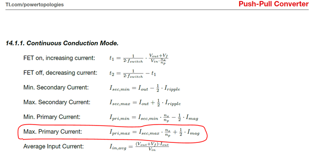
    refer below figure

    since turn ratio is constant, then the maximum primary current is approximately constant. for more output current, customer has to re-design current transformer or smaller the sensing resistor of current transformer secondy side. but keep in mind: all these update need keep push-pull transformer safety in specification. feel free to let me know if you need further supporting. thanks.

    regards,

    Bill 

  • Thank you for your answers.