This thread has been locked.

If you have a related question, please click the "Ask a related question" button in the top right corner. The newly created question will be automatically linked to this question.

TIDA-01606: Gate driver board connection

Part Number: TIDA-01606

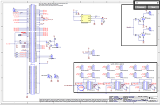
I have some question about gate driver connection.

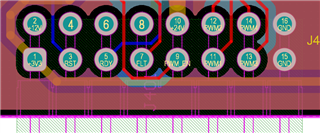
When I checked the schematic and PCB file, it is different. 

Which one is correct? 

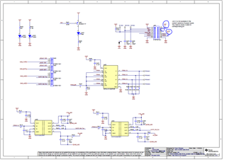
And also, there is LI_and HI_PWM connection in the main board to gate driver.
I am not sure what purpose of LI_and HI_PWM are

Best regards,

  • Hi

    the right 24 V, which is actually also used by the DCDC converters is the highlighted pin number 10.

    LI_and HI_PWM are there because in the previous version we were creating the isolated power supply for the gate drivers by means of local converter which was using these two high frequency signals. These two signals are not anymore used in the new converter.

    Thanks

    Best Regards

    Riccardo