This thread has been locked.

If you have a related question, please click the "Ask a related question" button in the top right corner. The newly created question will be automatically linked to this question.

TIDA-01606: Rectifier Experimental Problem

Part Number: TIDA-01606

Hi Team,

There's an issue from the customer need your help:

I built a TIDA01606 hardware platform for experiments, and the off-grid on-load experiment was normal, but there was a problem when I did the grid-connected rectification.

On the AC side, I connected a three-phase voltage with an effective value of 20V, and a 100 ohm load on the DC side, pre-charged the DC bus capacitor before the experiment began, and then waited for the phase locking to be completed

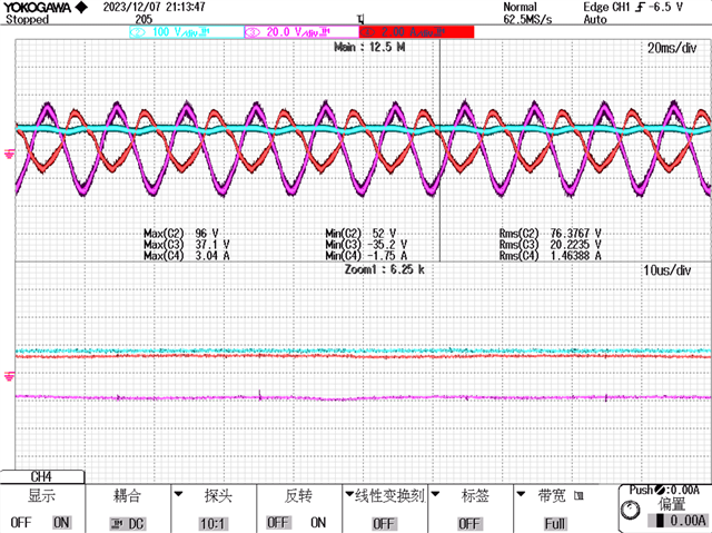
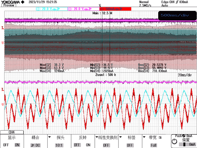
After closing the relay, we are conducting a rectification experiment, which simulates that the three-phase voltage emitted by the power grid is biased and the current is non-sinusoidal (the oscilloscope waveform diagram is shown below). Point N on the grid side is not connected to N on the grid, and the relay remains disconnected during the relay pick-up operation

Thanks & Regards,

Ben

  • Hi Ben,

    I am not sure if you connect with the right sequence the three phase inputs.

    If you connect on the wrong way like swapping the phases it will no work.

    Thanks

    Best Regards

    Riccardo

  • Hi Riccardo,

    Customer confirmed that there is no error in the three-phase connection, phase-locked loop phase-locked out of the angle is also normal.

    Best Regards,

    Ben

  • Hi Ben,

    apologize if I re-ask but I would like to re-ask more in detail since I have the same issue in the past with this reference design.

    I have again the following question:

    • If you connect L1, L2 and L3 of the grid emulator to the ABC of TIDA-01606
    • is the customer working with a grid emulator having positive or negative sequence? if it has negative sequence this will be a problem :)

    What is the voltage that you are trying to control on the DC link? 60 V?

    Thanks

    Best Regards

    Riccardo

  • Hi Riccardo,

    Customer can be sure that there is no error in the phase sequence of the grid simulator's three-phase voltages ABC connected to ABC on the power board, he have simulated that if it is wrong park converted D will be wrong.

    Best Regards,

    Ben

  • Hi Ben,

    it was also a problem of PLL as far as I remember when I was doing tests when you connect a three phase grid with different sequence.

    I would like to ask you what is the current DC bus voltage setting.

    Thanks

    Best Regards
    Riccardo

  • Hi Riccardo,

     the problem seems to have found, today I found the AB phase drive Q4 Q3 at the DC-DC conversion lamp did not light, I tested and found two mosfet gate source pole short circuit, mosfet bad, I replaced and then did a little experiment, in my reference current to the reference current has not been cut into the load, the AC to the rms value of the voltage 20V, the DC voltage rises to 500V, after the second experiment, I cut the load to the reference value of the current to give the order of the reference value, to get the C-phase of the voltage and current, as well as the value of the DC bus voltage is shown in the following chart, this kind of is normal, right.Voltage in purple, current in red 


    But the current is not balanced and I don't know what causes it

    Best Regards,

    Ben