This thread has been locked.

If you have a related question, please click the "Ask a related question" button in the top right corner. The newly created question will be automatically linked to this question.

PMP8740: P-MOSFET Gate Source Resistor Selection

Part Number: PMP8740

Dear TI Experts,


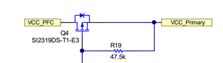
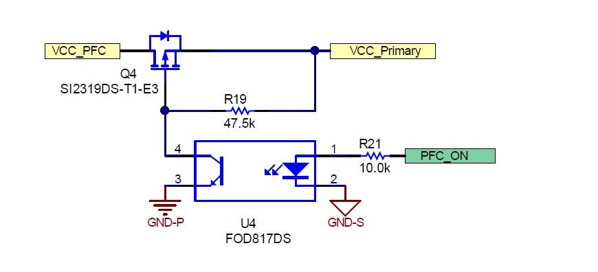
How is this Pull-up Resistor from gate to Source selected? (47.5k)
Based on the MOSFET's Gate Charge (Q) or (CISS)?  Can you share the basic equation to select that resistor value based on MOSFET parameters for the same application? 
Also, Is there any role of the Optocoupler's Open Collector transistor?

The application is only to Turn ON or Off. (No High Switching Application)

Thanks & Regards,
Meet Devendra Pandya

  • Dear Meet, 

    You are correct: the application of this section is only to turn on or off the PFC stage. It's not a high frequency switching application, just enabling or disabling the PFC stage, therefore both delays, turn-on and turn-off, can range milliseconds or even tens of milliseconds. Now the Ciss or Gsg of Q4 do not play any role. The only parameters that we have to take into account are the CTR of optocoupler U4 (see attached section of this schematic) and eventually its "dark current".

    Parameter CTR: when pin 4 has very low voltage (the saturation voltage is here ~ 100 mV - 200 mV), the current flowing through R19 is Vr19 = VCC_Primary (12V) - Vce(sat) = 12V - 0.2V = 11.8V. Now this current is Vr19 / R19 = 11.8V / 47.5 kOhm = 248 uA. Now let's suppose that CTR reduction due to low IF current gives a reduction factor of 40%. At this point the real CTR will be 300 % - 600 % times 40%. It means it will be in the range 120% - 240%. Let's consider its minimum 120% in order to take some margin. Now, the primary current (emitter side) is 248 uA / 1.2 = 206 uA. Knowing now the emitter's current, we should verify on the CTR reduction curve that it is ~ 40%, and if you extrapolate the curve, it should intersect 40%. Now we can calculate the resistor value of R21 = V(PFC_ON) - VF(emitter) / 206 uA. = 3.3V - 1.2V / 206 uA = 10.19 kOhm, where V(PFC_ON) is the output of the microcontroller's digital output and 1.2V is the drop on the emitter diode. As you can see I selected 10 kOhm, considering that I took the margin on the CTR.

    I hope that explains the calculation. If not, please let me know.

    Regards,

    Roberto