This thread has been locked.

If you have a related question, please click the "Ask a related question" button in the top right corner. The newly created question will be automatically linked to this question.

TIDA-01606: TIDA-01606

Part Number: TIDA-01606

Hi Expert

I just have project to design Active Front End (AFE) based on TIDA-01606, i just want to eliminate T-type architecture and replaced with standart 2 level 3phase bride inverter, i have done detailed simulation on PSIM shown below


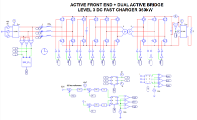
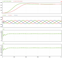
with promising result, I believe with view modification firing angle provide by Ti on TIDA-01606 we could modified the T-type version to standar 2 level 3ph Bridge for the sake hardware simplicity due to availability power module available on the market

I have simulated also T-Type PFC on PSIM. I knew excactly how to firing T-Type Bridge and 2 Level Bridge

my problem was i relative new to C2000 ecosystem, i believe just modified this line code would solve the problem due to this code contain PWM update or Firing scheme for T-Type version

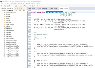
Probably asking to Ti expert would solve my confusion, please explain how to modify PWM update for 2 level bridge inverter, i wouldnt touch the control algorithm because i believe only just modifty firing scheme would solve the problem

Thank you

BR

Abdin

  • Hi Abdin,

    thanks for reaching out. As far I understand, you would like to implement a 2-level by using our C2000 control card as 39C or 379D but you would like to keep the same high level control scheme diagram.

    Am I correct?

    Thanks

    Best Regards

    Riccardo

  • Hi Riccardo Ruffo

    Thanks for follow up

    yes correct, i want to convert T-Type PWM IGBT Firing to Just 2 Level H-Bridge IGBT Firing for the sake simplicity.

    I believe all code in TIDA-01606 including close loop current control, etc still the same and just replace PWM update routine from T-type firing into 2 level H-brige

    i didn't quite understand code below T-Type PWM update due to lack of knowledge C2000 PWM Hal routine, maybe i will learn completely about PWM HAL routine, hardware etc for C2000 especially 39C or 379D


    Thanks 

    BR

    Abdin

  • Hi Abdin,

    in general, I believe you can just take a PWM unit which has complementary output with deadtime implemented. You will give to this PWM unit a duty cycle which will be between 100 % and 0 %.

    e.g. I give 60 % to the PWM unit, this means top switch is on 60% of the time and bottom switch 40 % of the time (of course include also the dead-time!)

    In order to interface the existing code, you will need to to rescale the output of the controllers. The existing code gives you a value of duty cycle which is between 1 and -1 (TINV_duty_A_pu, TINV_duty_B_pu, TINV_duty_C_pu). So you will probably need to give to the PWM unit the following value = 0.5*(TINV_duty_A_pu+1)*100%

    Please remember you need three PWM units because you have three-phase system.

    Thanks

    Best Regards

    Riccardo