Other Parts Discussed in Thread: UCD3138A, UCD3138, PMP
Hi,guys.
I'm having a problem and I need some advice.
Hardware:PMP23340UCD(UCD3138A)
Firmware:TI supplied routines——UCDIBCFirmware


Goal:I need to take some measurements. Therefore the frequency and dead time of the DPWM need to be adjusted.
Issues:
- Can I do this through the GUI?What exactly should I do?
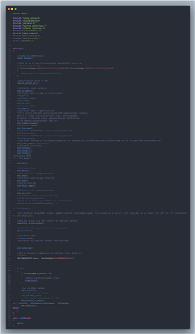
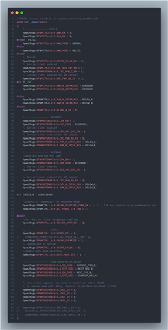
- Currently I'm just starting to learn UCD3138.Can I set DPWM to normal mode in the source code and disable CLA_EN and comment out the other functions?
- Can I write a simple program to control it via DPWM only (no filter, front end).
- Four switches on the primary side, two switches on the secondary side, how to set the phase and trigger between the three DPWMs?
- Do you provide DPWMC 、Edge Generation、IntraMax related information, the description on the datasheet is a bit succinct.
I would like to implement frequency or dead time debugging via GUI on the source programme.
But the complexity of the procedure makes me not know where to change it, and I'm afraid of destroying the functionality of the source programme.
If I can't change it on the source program, can I write a simple program to just control the DPWM to achieve it.
And I'm experiencing confusion about the way to drive the primary and secondary switching tubes.In particular, internal multiplexing and edge triggering.
If I only drive the dpwm, will I be able to achieve what the board does - the same output at the same frequency as the source programme!
Sorry for the vague description, can you give some suggestions and ideas based on my question?
Best Regards.

