This thread has been locked.

If you have a related question, please click the "Ask a related question" button in the top right corner. The newly created question will be automatically linked to this question.

TIDA-050063: Negative current when precharging

Part Number: TIDA-050063
Other Parts Discussed in Thread: TPSI3052-Q1,

Tool/software:

Hello,

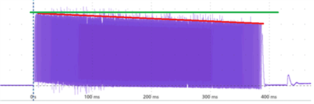
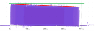
I have noticed in the refernce design that the current amplitude is rather consistent trough the precharge cycle but there is a small slope on it. (see the red line in the picture below from the reference design, Figure 3-4).

In my application, I need to reduce the inductor size and therefore have a much smaller saturation current and consequently a lower current swing. I have therefore decided to use 2.5A as my upper limit and 0.5A as my lower for the target value in the feedback loop. It seems that the lower the inductance the more aggressive the angle of that slope gets. In my simulations it now looks like I'm getting quite a lot of negative current spikes (charging the battery). (~400mA). 
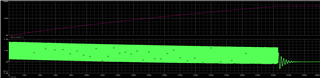
This doesn't seem realistic to me and I don't know what implications it would have. Could you please shine some light on:
-Where does this slope come from?
-What are the implications of the negative charge current?

I attached the graphs from the simulation and a picture of my simulation setup. Let me know if you need anything else.

Best, 

Emil
 plot1 (1).pdf
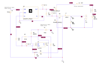
  • Hello Emil,

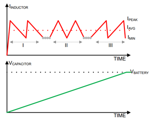
    Thanks for reaching out to our team on E2E. The slope behavior was tricky to understand but it's due to a combination of the current's slope changing and comparator response time. 

    Initially, the current rise is at its sharpest and current decay is at its slowest. However, towards the end of the charging cycle the current slope is at its slowest and the current decay is at its sharpest. So at the beginning of the charging cycle (I), the current will overshoot the most during the "current rise phase". Whereas at the end (III), the current will overshoot the most during the "current fall phase".

    -What are the implications of the negative charge current?

    I think this could potentially increase the needed charge time but the diode should prevent too much reverse current flow from happening. In terms of charge time, the higher initial average current should balance out with the lower ending average current. Would be good to also double check the inductor specs and make sure it has margin.

    A larger concern here is the narrow charging current window, 0.5 A to 2 A. The TPSI3052-Q1 would needed to provide a lot of power in order to drive the needed switching frequency here. What are your system specs (voltage, capacitance, required charge time)?

    Best regards,
    Tilden Chen


    Solid State Relays | Applications Engineer

  • Hello Tilden,

    Thanks for the quick answer.

    The current slope thing does make sense. Thanks for pointing it out!

    Yeah, I'm struggling with those design parameters but I will see if it's possible to make the inductor I chose work.


    I think I still need some help with understanding the negative current. I wonder if it is representative of how the circuit behaves in real life. I don't understand how the inductor isn't just "emptied of energy" and if anything the "overshooting" should just lead to a DCM-type of behavior (spots with 0 current).

    I can add that the negative charge current (current discharging our precharge capacitor) is going into the battery in my simulation. 

    I will re-run the simulation tomorrow and check how D2 behaves at this point.


    Best,

    Emil
     

  • Hello Emil,

    Thanks for the update here. Wanted to point out that the Pspice project uses an ideal 15 V source which does not account for the TPSI3052-Q1's limited power transfer. I need to update it, but we should be able to replace it with the TPSI3052-Q1 model now and connect to VDDH as how it is connected in the actual system. At the time I made the Pspice project, there were model compatibility issues which have since been fixed.

    Best regards,
    Tilden Chen


    Solid State Relays | Applications Engineer

  • Hello Tilden,

    I am running into a similar problem and I was wondering if you could please send me the updated Pspice project with the TPSI3052-Q1 included whenever you are done. 

    Thank you,

    Grant McKechnie

  • Hello Emil, Grant,

    Thanks for your patience, let me take a look tomorrow morning and get back to you both.

    Best regards,
    Tilden Chen


    Solid State Relays | Applications Engineer

  • Running into convergence issues when I add the TPSI3052-Q1 to the TIDA-050063 project. Need more time to look into this. 

    Best regards,
    Tilden Chen


    Solid State Relays | Applications Engineer

  • Reaching out over private message to connect over email.

    Best regards,
    Tilden Chen


    Solid State Relays | Applications Engineer