This thread has been locked.

If you have a related question, please click the "Ask a related question" button in the top right corner. The newly created question will be automatically linked to this question.

TIDA-01385: Design of a self powering AC current sensor

Part Number: TIDA-01385

Tool/software:

I want to design a self powering AC current sensor with following Concept: 

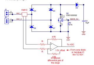
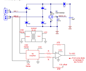
This self-powered AC current sensor should consists of a split-core current transformer and is supplied via an AC conductor. The sensor is to supply itself, i.e. the Loxone Air module (MCU + transmitter unit), through energy harvesting. When enough energy has been harvested, the system switches to measuring. This means that the harvesting part is switched off and the current transformer is switched to a shunt resistor, from which the voltage drop is measured and thus the current can be inferred. As alternating current comes from the current transformer and only the RMS is to be measured, an "RMS to DC converter" may also be necessary before the value is read in by the ADC of the MCU. After recording the current value, the MCU goes back into sleep mode and the sensor is back in harvesting mode. Excess energy is to be stored in a supercapacitor for times when no primary current is flowing. The MCU should be woken up again for the next measurement using the wake-up pin. If possible, the MCU should send a "last will" before it runs out of energy completely. When current flows again and sufficient energy is available again, the MCU should restart.

Are there any reference desins from TI, or how could so a design look like. Are there any usefull components from TI that I can use for this sensor etc. 

How can i solf this problem and how can dies cirucit look like. 

Thanks for your help ;)

  • Hi Jonas,

    I'm not sure which part of the concept are you having trouble to design. The MCU part is not hard to be designed and so is the CT harvesting circuit (TIDA-01385 has CT harvesting circuit already).

    So I'll be answering the RMS to DC part:

    Usually there're two ways to get the RMS value from AC signal, both ways requires a DC-offset for the AC signal sampling:

    When your MCU samples the AC signal, the most simple way is to save the AC current in memory and calculate its average value every 50Hz(60Hz if your region applies 60Hz grid). Then you can calculate RMS value by RMS=1.11*AVG for ideal sine wave.

    The other way is to calculate the real RMS. For example, you sampled 400 times within every cycle of your AC grid (N=400) and every time you'll get a u1,u2,u3,...,u400 (sampled result). Then your RMS value can be given by:

    Best Regards,

    Travis

  • Hi Travis,

    Thank you for your reply. At the moment, my focus is on the energy harvesting and power management parts, but the measurement is also an important aspect of my project.

    For the measurement, I am using a current transformer, not a Hall current sensor. A current transformer delivers a current and should be connected to a low resistance (shunt resistance). In your circuit above, the current transformer is connected directly to the OPV, which typically has a high input impedance and should not be connected directly to the current transformer. Therefore, a shunt resistance would be needed.

    Do you have a design for the power management as explained above?

    Thanks and best regards,

    Jonas Koblmüller

  • How can the switching between harvesting and measurement be handled, ensuring that the harvesting part from the current transformer is disconnected and switched to the shunt resistor for measurement? Also, how can the circuit be designed to incorporate wake-up and last-will functionalities?

  • Hi Jonas,

    Apologize for the late reply. It took us a little time confirming the responsible organization for this design and now I'll be taking this thread.

    It'll need extra iso circuit to sample the AC secondary current because the CT (VAC1,VAC2) is not common grounded with your control circuit:

    So there're several ways to sample the AC current:

    1.sample the rectified current to calculate the RMS value. This will be a rough sampling because of the Vf of the rectifier diodes. But this rectified current can be measured on the same ground with your MCU so you won't need isolation circuit.

    2. The other way is to apply an hall IC. 


    3.You can replace the hall with an isolated amplifier, but an isolated amplifier needs power rail for both front side and back side so this will be the hard way:

    Best Regards,

    Travis