This thread has been locked.

If you have a related question, please click the "Ask a related question" button in the top right corner. The newly created question will be automatically linked to this question.

TIDA-01487: TIDA-01487 communication issue

Part Number: TIDA-01487
Other Parts Discussed in Thread: TCAN1042HG, SN74LVC2G132, SN74LV132A

Tool/software:

Hi team,

Based on TIDA-01487, the attachment is the schematic design of a non isolated CAN relay that customers have modified.

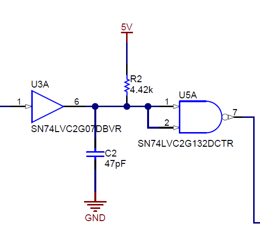
The current debugging situation is that after connecting communication devices to TCAN1042HG, the buses on both sides are usually set to a fixed level after a short period of CAN message waveform. The capacitor C6 C8 and resistor R6 R7 in the delay section were attempted to be modified to 4.42k and 47pF, which are consistent with the reference design, but still cannot work properly.

Could you kindly help analyze the possible reasons and provide suggestions for us?

Thank you!

CAN中继设计.pdf

Regards,

Maggie

  • Hi Maggie,

    Thank you for your question.

    At which CAN speed does the issue occur? Can the customer test a lower CAN speed overall, to see if the principal arbitration logic is working correctly? 

    Overall I saw in the schematic the use of LV devices. We use in TIDA-01487 LVC devices, which have a low propagation delay. I think low propagation delay of the arbitration circuit is needed to achieve high CAN speed.

    Regards,

     Thomas

  • Hi Thomas,

    The CAN frequency we tested was 57.6K, which is relatively low. In this situation, we still cannot establish a suitable CAN communication connection.

    In addition, the LVC series materials currently used by our customers don't support the working condition of Vcc=5V, so it may be difficult to replace and test them.

    Currently the project is quite urgent, could you kindly give some suggestions to us?

    Thank you!

    Regards,

    Maggie

  • Hi Maggie,

    I think the customer needs to validate the function of the arbitration circuit first. Here are two items to check.

    1. In TIDA-01487, we use for a 2-Input NAND Gate With Schmitt-Trigger Inputs for U3. I don't see in customer schematic the part name for U3. Please confirm with customer that this is a device with Schmitt-Trigger Inputs.

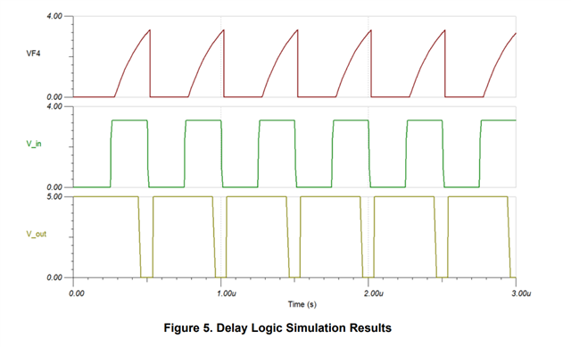
    2. With respect to TIDA-01487, they need to measure with a scope the signal delay from U3A input, U3A output, and U5A output. They should measure both delay circuits on the board (independently), to confirm that we see here the expected delay from input to output.

    In the TI Design guide this is Figure 4 and Figure 5.

    Let us know the outcome of the two questions below.

    Thank you and regards,

     Thomas

  • Hi Thomas,

    Thank you for your reply!

    The reference design uses a NAND gate with Schmitt trigger. The current customer design does use a device without Schmitt trigger input (SN74LV00APWR). We think this may be the main reason for the functional abnormality. 

    Customers found found a four-channel NAND gate with the part number SN74LV132A. Can this device meet the functional requirements of SN74LVC2G132 in the reference design?

    Thank you!

    Regards,

    Maggie

  • Hi Maggie,

    The LV logic has higher switching characteristic vs. the LVC logic (LVC is faster). Both devices should work in the arbitration logic, where the LVC does support a higher CAN baudrate in the design.

    Regards,

     Thomas