This thread has been locked.

If you have a related question, please click the "Ask a related question" button in the top right corner. The newly created question will be automatically linked to this question.

PMP30183: PMP30183 25A peak for 10msec

Part Number: PMP30183

Tool/software:

 Hello Ti Team,

I am going through PMP30183 reference design.I

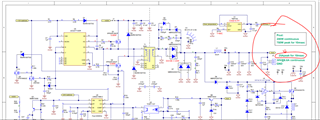
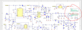
In the below PMP30183 schematic it is mentioned that output will support 25A peak current for 10ms time .


Output C10,C11,C12 capacitors will support the  25Apeak current for 10ms time??? can you check and confirm it.


Thanks,

Karthik


  • Hello Karthik,

    The modulation for this converter is peak current mode with cycle by cycle current limit. This means that as soon as Iout reaches the maximum current, there will be a limit on the charging current for all output electrolytic capacitors. The peak current limit on primary side is set so that Iout(max) is 25A. When Iout = 25A or more, some current will be supplied by the capacitors, and some other by the converter itself. If you have a look to the test report, there is a certain loop bandwidth, let's call it Fco (crossover frequency). The output impedance of the converter can be simplified to be Zout = 1/(2πFco*Cout); then multiply this impedance by the output current transient and you get the output voltage variation during this Iout transient. Please let me know if that answers your question.

    Thanks,

    Roberto

  • Hello Robert,

    No i have asked the converter output is designed to deliver 6.6A continuous current.The peak current on 25A can support of 10ms .Is the Output C10,C11,C12 capacitors are delivering that and how it was calculated

  • Hello Karthik,

    The electrolytic capacitors C10, C11 and C12 are delivering the whole output current (25A) during the time feedback is not able to follow Vout variation, so for short time only. In fact, according to the settling time of the converter (see section 9 of the test report), which is ~ 10 msec, Vout will be recovered to nominal value. Now, if you have a look to this transient response behavior, Vout deviates by ~ 100 mV with a 10A delta-current on the load. Let's verify that with the formula I described (Zout = 1/(2πFco*Cout)). Here Fco is 4.793 kHz (see section 10 of the test report), when Vout = 30V (high output power setup).

    If we calculate now Zout, we get 11.058 milli-Ohm. This impedance multiplied by 10 A transient load current gives 110.58 mV, which is the voltage drop we measure in the transient response screenshot. If you have now 25A transient load, you can multiply it by the impedance and get 276 mV, which is 0.92% of Vout (if I remember that correctly, I calculated Cout to have maximum 1% delta-Vout). Anyway this is not 100% correct, because with 0 to 100% load transient, the converter crosses both boundaries of DCM and CCM (where the loop compensation changes between these two modes) and the fact that for this high load current a better analysis should consider large signal analysis and output inductor slew rate calculation. You can find more info about this last topic by published articles about transient in Buck topology. If you need some further documents about Buck topology and transient response, just let me know I will send you some of them.

    Best regards,

    Roberto

  • Hi Robert ,

    Can you please share that transient in Buck topology reference document .so that i will go through it.

    My application requirement is :

    output voltage VOUT=28V with 10% regulation  during full and  peak load .

    Buck converter full load output current of 7.5A.

    And i have to support  peak load of 9A current for 50ms to the load.

    Ripple voltage 2% of Vout is acceptable.

    Now  output capacitor C= ((Vin-Vout)* D)/(8*L*F^2*ΔV) i calculated for BUCK converter equation.

    and to support 9A which is (7.5A+1.5A) 7.5aa will be supplied by converter the extra 1.5A current should be supplied by output capacitor.

    so by using  Energy =P *Time and E=1/2 C V^2 i can calculate the required output capacitance know???

    Also during 9A peak load for 50ms the output voltage should be 28+ 10% and output voltage ripple  should be less than 2%.

    How can i do this calculation ,Can you help me out and with load transient condition.

  • Hi Karthik,

    Please refer to the document:

    Under the hood of low-voltage DC/DC converters white paper, where section F shows how to select the output capacitor of a Buck converter.

    Also the following interesting video is useful for this topic:

    https://www.ti.com/video/6101963066001?keyMatch=Under%20the%20Hood%20of%20Low-Voltage%20DC/DC%20Converters&tisearch=universal_search

    If in your case the Buck converter is able to supply only 7.5A (I hope by limiting it in cycle-by-cycle current limit, otherwise during these transients this converter will switch off) and 1.5A come from the output capacitor during 50 msec, then I agree that you can calculate this capacitance according to the formula with energy in a capacitor.

    Regards,

    Roberto

  • Hi Robert ,

    Yes, i my case what you mentioned above post  lines  are correct(Buck converter is able to supply only 7.5A (I hope by limiting it in cycle-by-cycle current limit, otherwise during these transients this converter will switch off) and 1.5A come from the output capacitor during 50 msec)

    My application requirement is :(already mentioned in previous post)

    (Output voltage VOUT=28V with 10% regulation  during full and  peak load ,Buck converter full load output current of 7.5A and i have to support  peak load of 9A current for 50ms to the load ,Ripple voltage 2% of Vout is acceptable.)

    But i have doubt in the calculation,

    Energy =Power *Time, Power =VOut * I=28V*1.5A= 42W==> required 42W from capacitor.

    Energy=42*50*10^-3=2.1joules

    Energy=(1/2*C*V^2)

    C=(2*E)/V^2

    Delv^2= 28^2- 27.44^2=31.046( considered 2% of 28V drop= 27.44)

    C=(2*E)/V^2==>2*2.1/31.046=0.1352F which is 135281uF very high value 

    there is wrong in this i am getting doubt as it is high value because....

    PMP30183

    For 25A,30V for 10ms which is 750W power has only 3000uF output capacitor with C10,C11,C12 capacitors.

    How i can get 1.5A ,28V for 50ms get very high value of 135281uF ????

    can you please check and correct me if i did any mistake in calculation considration.

  • Hi Karthik,

    Your calculation looks correct when supporting 1.5A extra current for 50msec out of an electrolytic capacitor at 30V, supposing Vout drop is less than 2%. The difference with PMP30183 is that in your case this extra current is drawn without the possibility for the Buck to replenish it (or recharging it during 50 msec). For PMP30183, the converter is able to deliver up to 25A continuously, so, in theory, if the bandwidth of the converter is infinite, there is no need of output capacitance, and it can be selected practically zero!! Since a infinite-bandwidth converter doesn't exist, we need to add Cout that is able to support transients, avoid generating voltage ripple, and that is able to support also the inductor ripple current. So, this 3000 uF is there mainly to support Vout during transients. Now if the DC/DC stage of PMP30183 is loaded at 25A longer than 10 msec, then the primary side overcurrent protection will be triggered and Vout will drop to zero (then a new soft start initiated). I hope that explains my thoughts :-).

    Regards,

    Roberto