Tool/software:
Hi Expert,
Recently, my customer is studying the phase locking program, so I would like to ask some questions while referring to the TIDA-01606 program.
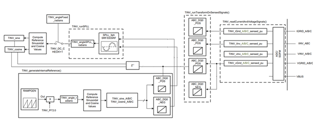
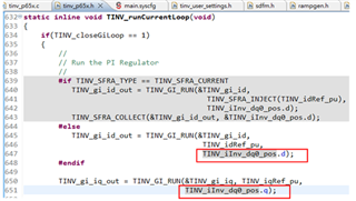
1. Is the red box in Figure 1 an error in the drawing, because it should be the inverter current in common sense, or is it because the grid current of TIDA-01606 is almost the same as the inverter when connected to the grid in inverter mode. The two interchanges are Is there any problem? In the program, the inverter current command is used, as shown in Figure 2.
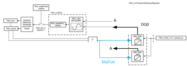
2. The red line in Figure 1 should be marked right? The value read by the ADC should be converted to the omega of the DQ axis after scaling, and the angular velocity output by the SPLL should be used, right?
3. If the TINV_DC_CHECK in the blue box in Figure 1 is 1, what signal is it to confirm? Because I see that the program is placed in the user setting. If it is set to 1, it will directly output a fixed angular frequency to the entire system, so I I think the direction of the relay should be reversed. But I still don’t understand what signal we need to confirm after outputting the fixed angular frequency to the system?
Figure 1
Figure 2
Best Regards,
Seamus