


Tool/software:
Hello,
I am doing some tests to get more confidence on stability and phase margin measurement usingTina TI.
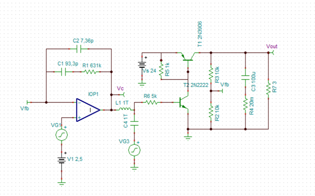
My circuit is a linear voltage regulator (24V to 5V, fixed output):

The 2.5V reference (V1) set the 5V output.
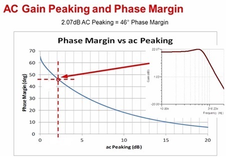
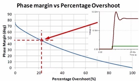
The aim of my tests is compare the loop phase margin measurement with the "indirect" methods: the overshoot of the small step response and closed loop AC peaking measurement.
I use these two graphs as reference:
VG1 performs a 10mV step, to check the Vout time response.
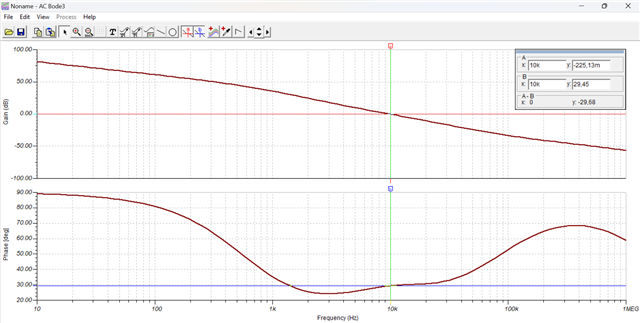
The compensation stage performs a type 2 network, with a phase margin of 70°. I have verified this "opening the loop" in this way:
VG3 performs the AC sweep and I get the following open loop response measuring Vc:
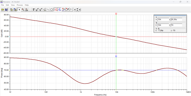
So, the 70° of phase margin are confirmed.
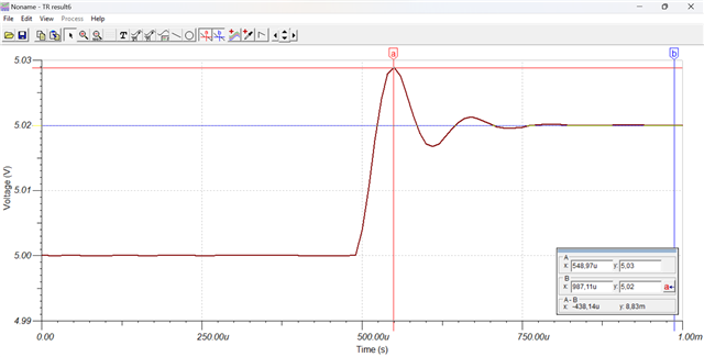
But, if I apply the 10mV step to the orginal circuit I get this overshoot on Vout:
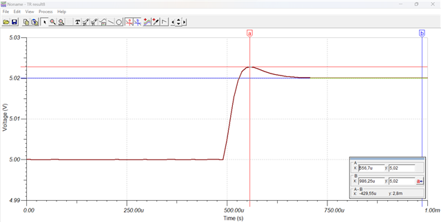
The % overshoot is 100*2.8/20 = 14% that is typical of a phase margin of 55, quite different from the 70° of open loop measurement.
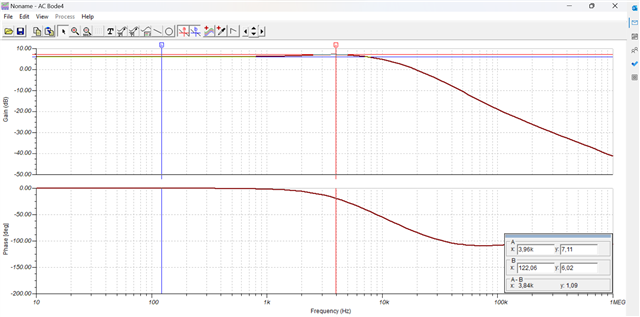
As regards closed loop AC peaking, I obtain 1.09dB that correspond to a phase margin of about 53° (quite close to that obtained with the step response).
2nd TEST
I have modified the compensator to obtain a 60° PM:

The open loop confirms that:

Now, if I apply the 10mV step, this is the Vout:
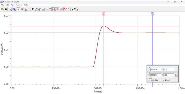
The % overshoot is 100*4.04/20 = 20.2% that is typical of a pahse margin of 48° quite different from the 60° of open loop measurement.
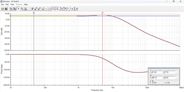
As regards closed loop AC peaking, I obtain 1.72dB that correspond to a phase margin of about 48° (the same obtained with the step response).
3rd TEST
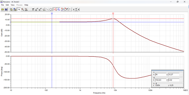
I have modified the compensator to obtain a 30° PM:

The open loop confirms that:
Now, if I apply the 10mV step, this is the Vout:
The % overshoot is 100*8.83/20 = 44.15% that is typical of a pahse margin of 25°, not so different but not equal to 30° of open loop measurement.
As regards closed loop AC peaking, I obtain 6.25dB that correspond to a phase margin of about 28° (quite close to that obtained with the step response).
So, in summary, the two indirect methods show similar results but both differ from the direct measurement of phase margin using the open loop transfer funcion.
To be sure, I have also measured the phase margin opening the loop between R3 and Vout and I found the same exact values of that.
Could you explain to me what I'm doing wrong?
Thank you and regards,
Massimo
