Because of the Thanksgiving holiday in the U.S., TI E2E™ design support forum responses may be delayed from November 25 through December 2. Thank you for your patience.

TIDA-010242: The TIDA-010242 design - how to increases support current

Part Number: TIDA-010242

Tool/software:

I am referring to the TIDA-010242 reference design for my 28V system. My system requires 500W. As I understand from the disturbance limits information, the minimum voltage is 12V (1s).

Do I need to ensure that the system can handle 500/12 = 42A?

Additionally, according to the TIDA-010242 design, what parameters should I consider to achieve my target?

  • Chin,

    You are correct that the starting disturbance is 12V for 1sec, 16V for 30sec, and then 20V for 2sec.

    The amount of current that the the surge protection design needs to pass through during this disturbance is entirely dependent on the downstream power stage and system. I cannot broadly comment on how much current it will need when operating at 12V without knowing more. If you are looking at worst case scenario, and it is a static 500W load, independent of input voltage, then yes, you should expect to pass 42A during the disturbance; however I cannot gurantee that to be the case.

    Regarding designing to a higher power level for nominal operation, you can begin by referring to section 2.2.6 of the design guide. This walks though the process of selecting the appropriate MOSFets to be able to handle the surge currents. You will need to use the MOSFet datasheets to determine their SOA and ensure they will function appropriately during the surge events. There is a link to a calculator for the SOA on this thread that might be useful to you: https://e2e.ti.com/support/tools/simulation-hardware-system-design-tools-group/sim-hw-system-design/f/simulation-hardware-system-design-tools-forum/1273198/tida-010242-tida-010242?tisearch=e2e-sitesearch&keymatch=TIDA-010242%252520excel#

  • Dear @

    Thank you for your suggestion.
    I'm following the SOA calculator and have some questions.

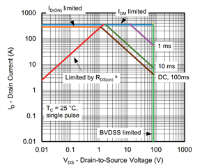
    Firstly, I chose this MOSFET for my design. You can see more details here: https://www.vishay.com/docs/63064/sijh800e.pdf

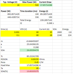
    When check the SOA, Do input values is correct ?


    Secondly, my question is related to "ROCA."
    Is it RthJC, or do I need to calculate it manually?

    Finally, my results are as follows.
    But I don’t know how many MOSFETs in parallel I need to implement to achieve my design specifications.

    Thanks
    BR

  • Chin,

    A few notes on your reading of the SOA graph. You should be looking at 50V, not 80V, as this is the clamping voltage of the FET in the design. Even at 80V though, the current at 0.1sec should be about 4A, and at 0.001s is close to 55A. If you use 50V as the mark for this reading, then they would be 7.5A and 88A respectively. These numbers would put the computed SOA only around 4.4A total at 25C.

    Regarding ROCA, it is RthCA, not RthJC. While semi related via RthJA as well, these are not directly correlated with modern packaging. Functionally though, we are looking for Tc, which is a datasheet parameter. If the values in the datasheet for the given temps work for you, you can replace it in the equation to calculate SOA(Tc). We have an older, but still relevant application note about semiconductor thermals here if you want to read more: https://www.ti.com/lit/an/spra953d/spra953d.pdf

    Lastly, I do not have any information on using parallel mosfets in this application. Multiple of these in parallel might get hte performance you need, but I cannot comment on the ability of the driver to control it correctly due to variances in individual devices.

  • Hi Bart,

    Thank you for helping me solve my problem.