PMP20859: Request detailed Dual-input redundant circuit indication of PMP20859

Part Number: PMP20859
Other Parts Discussed in Thread: TPS2372, LM5020

Tool/software:

Hi Tier,

I would like to understand the detailed Dual-input redundant circuit indication of PMP20859. This will help us promptly address any issues during subsequent design verification.

Could you provide us with more comprehensive training documentation? Currently, we only have access to the test report.

if any concern, could share to my email address? wenyung.kuo@mag-meet.com
  • Hi,

    At this time I do not have a detailed description of the circuit.  Here is a general description of the major functions.

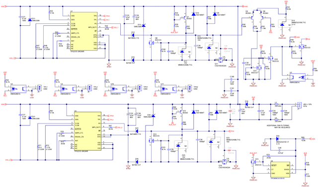
    The PG signals on the TPS2372 ICs keep the converter off until in-rush is complete.  This allows C25/26 and/or C35/36 to charge up before the converter starts switching.  The return of the TPS2372's and the converter are separated by D16/Q11 and D26/Q16  The Q5/Q6 circuit level shifts the PG signals since the PG return is not the same as the LM5020 return.  Optocoupler U2 disables the PG function once the output is present.  This prevents the PG signal from disrupting converter operation when one of the PoE inputs is connected.

    D16/Q11 and D26/Q16 block the opposite PoE voltage or the AUX voltage.  This allows each TPS2372 to detect the PSE, turn-on and remain in MPS (stay connected to the PSE) to allow seamless transition between the three inputs.

    When the AUX input is connected, U6 turns off Q11 and Q16, providing AUX priority.  If the PoE inputs are present, they stay connected to the PSE using the MPS function.  U6 activates at 40V input on AUX to provide seamless transition.

    There is a charge balance between C25/26 or C35/36 and C31 to allow the seamless transition.

    Thanks, David