TIDA-01599: Are isolation needed to archive SIL 3

Part Number: TIDA-01599

Tool/software:

Hello,

when checking the design a couple of question came up on my end.

In general my questions are linked to what is really needed to archive SIL 3. Reason for asking this is that we have a space and loss restricted application.

1. Are digital isolators are needed for the STO_1 and STO_2 signals?

2. When checking the standard, I have not recognized the need for implementing the STO_FB. Is my assumption correct that this was implemented to give users some feedback when they get familiar with the Eval board?

3. In our application we use non-isolated gate driver (48V application (MOSFETS are used in the bridge). Do you see any issues here with still reaching SIL 3

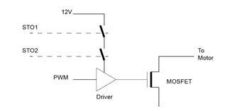
Here just some side information... As mentioned we are currently are using a non-isolated gate driver. In our current concept we still have two STO lines (STO_1 and STO_2). These signals are connected to a switch. The two switches (one for STO_1 and the second one for STO_2) are in series and will ensure that the supply of the gate driver will be disconnected when the STO gets low. (A simple version of this you can see in the following figure [  I am aware that diagnostic, filter, ... are not shown here])
Would be great if someone is able to answer them =)

Thank you

  • Hi Don,

         Thanks for your interest in TIDA-01599. Please find my answer: 

    1. Are digital isolators are needed for the STO_1 and STO_2 signals?

    [cgao]: It depends on your system design. In TIDA-01599, the STO triggering command is coming from external 24V stop of safe PLC which has different reference potential and different power rail for the STO logic signals that's why the digital isolators needed.

    2. When checking the standard, I have not recognized the need for implementing the STO_FB. Is my assumption correct that this was implemented to give users some feedback when they get familiar with the Eval board?

    [cgao]: The STO_FB signal is provided to indicate the status of the drive (safe state or normal operation) and can be used to feedback the status of the drive to a safety PLC for additional diagnostics, if desired. See table 2-3 of the ref.design.

    3. In our application we use non-isolated gate driver (48V application (MOSFETS are used in the bridge). Do you see any issues here with still reaching SIL 3

    [cgao]: The architecture should work but you have to run FMEDA for your safety system.

    Regards,

    Chen Gao