


Part Number: TIDA-01415
Other Parts Discussed in Thread: LM3409, , UCC27519, UCC27511
Tool/software:
-
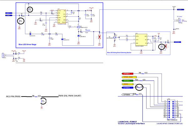
What exactly are the 10k resistors R7, R6; R20, R21; R44, R45; R56, and R57 for? I see they are in series with a 470-ohm resistor (which I also don't know the purpose of), connected from an MCU pin to the EN pin of the LED driver or the gate of the parallel MOSFET. What are they used for?
-
Regarding the 100k resistor connected between EN and VIN_LED on the LED driver, why is it there? The LM3409 datasheet states that EN should either be connected directly to VIN_LED or used for PWM dimming by applying a PWM signal.
-
Why is the UCC27511DBVR used, which has two outputs (OUT_H and OUT_L), instead of another similar part from the same family, such as the UCC27519, which has only one OUT? In this context, how are R3 and R4 calculated? I understand these are the gate resistors and that their value depends on the MOSFET, but I don’t know how to calculate them using a MOSFET's datasheet (or at least get an approximation).
-
The temperature differences observed in experimental tests I suppose that are due to the MOSFETs conducting more or less current; Is this related to variations in the MOSFETs Vgs(th)? Are the R3/R4 resistors included to compensate for these variations? Or has this not been considered in the design, and something additional needs to be done to address these variations?
Regards,
Renan
