TIDA-00948: Th PCB review and test items

Part Number: TIDA-00948
Other Parts Discussed in Thread: TPS54202

Tool/software:

Hi team,

TPS54202 is widely used in Hisense Air conditioner. They want to design TPS54202 in single layer. But it seems that our refer design TIDA-00948 layout is not very well. Could you please help check below questions and give feedback? Thanks!
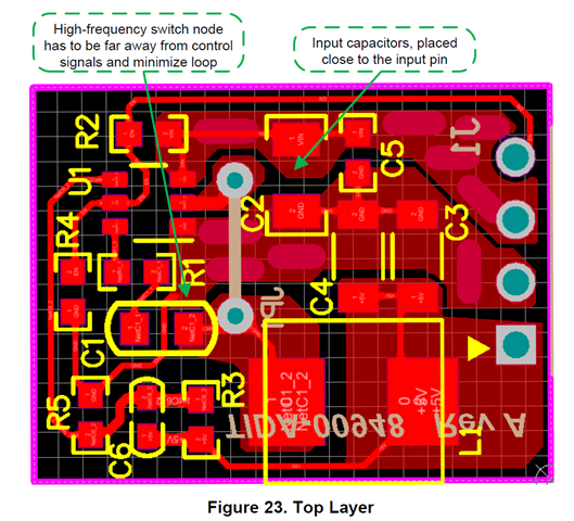
1. For the resistor R2 and R4, they should be close to FB pin, but the layout seems not. Is this ok?

2.For R2 GND, it is under the BOOT cap. Is it OK?

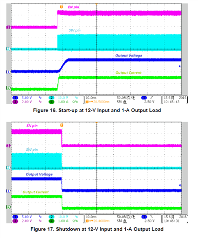
3.I tried to convince customer by test waveforms in user guide like below. But customer wonder can the device work well in -30℃ and 65℃ condition?
Regards,

Len

  • Hi Len,
    just saw your message. Will compare w/ EVM and d/s recommendation and come back w/ answer tomorrow.

    BR

    Bert

  • Hi Len,
    as stated yesterday, please see the following comments to your questions.
    In general: TIDA-00948 was done to showcase how commonly used large LDOs can be replaced by a much higher efficiency buck converter based solution with the same form factor as the former LDOs. That form factor influenced also the component placement on the TIDA-00948 PCB. Modification of the PCB, part placement and layout are possible in case customer isn't limited to use exactly the same form factor.

    Regarding your specific questions - I'll refer to the schematic shown on page 2 of https://www.ti.com/lit/df/tidrme9/tidrme9.pdf?ts=1733817448071

    1., 2. :   Output voltage divider R3, C6 and R5 placement is the most critical. The connection of those 3 components to the FB-pin (4) of U1 need to be kept as short as possible and as far as possible to the inductor L1 and BOOT capacitor  C1, R1.
    The top left corner of the PCB look for me to be a better place for R3, C6 and R5 and provides the shortest distance to  FB-pin (4) and a large distance to the inductor L1 and the boot-capacitor circuit C1, R1 .

    3. The TPS54202 is specified for -40 to +125C of operation, which includes the targeted -30 to +65C range. The thermal performance had been also evaluated in section 4.2.2 of the TIDA-00948 user guide https://www.ti.com/lit/ug/tidubx4a/tidubx4a.pdf showing a peak device temperature of 57C at 24C ambient, representing a delta of 33C. Applying the same delta to a 65C ambient would result to 98C, leaving more than 25C of margin to the max TJ of 125C. 

    BR
    Bert

  • Hi Bert,

    Thanks for the detail advice. Could you please help ship a TIDA-00948 board to customer for evaluating? Thanks!

    Regards,

    Len

  • Hi Len,
    great to see customers interest. I'll forward the request to the originators of the design as well as to our team.

    BR

    Bert

  • Hi Len,

    We don't have design board in our hand now, because this is a design from 8years ago. For this is a very samll and simple design, I think you/customer can build the board by yourself.

    Thanks!

    Jenson