LM5180-Q1: Light load regulation

Part Number: LM5180-Q1

Tool/software:

Hello,

While I am working on the TINA transient simulation of LM5180-Q1 downloaded from the TI website, I am having some issues after I made the modifications:

1. Increase the Rload to 500Ω

2. Increase the feedback resistor to 190k (~6V output)

3. Remove the optional Zener diode at the output 
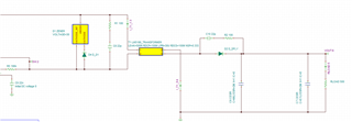
I noticed that the output is not regulated around 6V. May I ask some support to figure out what's the issue? 

Regards,

Alice  

  • Alice,

    -LM5180-Q1 has a minimum switching frequency fsw for light loads (see below). If no zener diode is connected at the output, Vout will loose regulation and increase because the controller will keep switching at 12KHz, providing a minimum power.

    - I recommend connecting back the zener diode at the output side or connecting a dummy load (moat likely lower than 500ohm). Please, use the Calculator Design to set a dummy load value for your converter.

    LM5180DESIGN-CALC Calculation tool | TI.com

    Thank you

  • Thanks Manuel. Now I update my design requirements:

    Input voltage: 13.5 ~ 14.5V

    Output voltage: 6V

    I use the WEBENCH tool to help with the transformer turns ratio selection, which is 1:1

    I follow your recommendations for light load simulation. 

    Feedback resistor: 63.5k (6V)

    Output Zener diode:6.8V

    Dummy load: 500Ω

    Transformer: 100µH 1:1

    Output capacitor: 140µF

    You can observe that the output is not stabilized ~6V. Any thoughts on how to improve? 

    Regards,

    Alice

  • Hi Alice, 

    -In your simulation results, it seems like Vout clamped 6.8V from the zener diode, which is what it is supposed to happen at light loads. Pout=Vout^2/Rload=72mW, which is very small compared with the full load/power rate.

    -You can try running simulation at lower dummy loads (e.g. 250ohms) and verify regulation Vout 6V.

    Thank you

  • Hi Manuel,

    Yes, lower the dummy load will solve the issue but at the cost of more losses. If my output voltage is flexible, do you see increasing the output voltage is better solution? For example, I setup the output voltage to 10V, I don't even need the dummy load or Zener diode based on simulation. Is that the actual case or do you still recommend having the same dummy load? 

    Thank you,

    Alice 

  • Alice,

    You can increase Vout and increase dummy load value. I always recommend a dummy load to avoid Vout regulation as the controller will switch at fsw_min=12KHz. If dummy load is not wanted, you can just use the output zener diode (zener voltage higher than Vout at steady state operation).

    Thank you

  • I meant to say increase dummy load...

    Thank you