This thread has been locked.

If you have a related question, please click the "Ask a related question" button in the top right corner. The newly created question will be automatically linked to this question.

TDC7200EVM:Time2 and onwards cannot be read correctly

Part Number: TDC7200EVM
Other Parts Discussed in Thread: TDC7201

Tool/software:

Hello
I am trying to do signal analysis using the TDC7200EVM.
Time1 can read the expected value, but the values ​​from Time2 onwards seem to be abnormal.
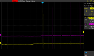
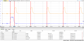
The yellow signal in the diagram is input to START, and the red signal is input to STOP.
The first pulse of the STOP signal is successfully detected, but the next pulse and beyond cannot be detected.
I thought that the first and second pulses that enter STOP after Start would enter Time1 and Time2, respectively, but is this wrong?
Or is it a hardware failure?
Please let me know.

  • Hello Kimura-san,

    Thanks for posting to the sensors forum! What do you mean by abnormal do you have any examples?

    If you are not getting a value have you made sure that the TDC7201 is programmed to receive more than one STOP event? If the device is only programmed for one STOP event then I believe it may not generate results for the subsequent STOP registers. Your assumption is correct but in order to do that the device needs to be programmed to receive more than one STOP event.

    Best,

    Isaac

  • Hello Issac,

    I am trying to make a program that will acquire five STOP signals. In the output example, the values ​​from Time2 onwards are acquired because the STOP event program has been created. However, it is unlikely that they will all be the same value.
    Is there anything I should be careful about in the program?

  • Hello Kimura-san,

    Is the delay between each of the STOP signals 1500 and 1600?

    The device shouldnt be measuring the same TIMEx for all the following STOP signals. Is this the raw data or has something been done to post process it here?

    Best,

    Isaac

  • Hello Issac,

    Yes, 1500[us] and 1600[us].
    The raw data is converted so that it can be easily output via serial communication.
    Does this mean that it is not okay to observe the STOP pulses being output at regular intervals, like in the oscilloscope image?

  • Hello Kimura-san,

    Thanks for the clarification. It is definitely okay to have the data output at regular intervals like the oscilloscope image its just not normal for all the data to display the same distance like what you are seeing for TIME2-TIME5. 

    I currently don't have the hardware to show you since I am not in the office due to inclement weather in Dallas, but on Monday I can show you what that the TIMEx for a capture like what you showed above should look like.

    Best,

    Isaac

  • Hello Kimura-san,

    This is what the your data should roughly look like for a capture similar to what you showed above.

    The first one is spaced 250ns from the start pulse and the rest are 1us away from there.

    The TIMEx values generated are the following-

    TME1: 4606

    TIME2: 23126

    TIME3: 41635

    TIME4: 60144

    TIME5: 78651

    with a normLSB = 0.0540346

    Best,

    Isaac