This thread has been locked.

If you have a related question, please click the "Ask a related question" button in the top right corner. The newly created question will be automatically linked to this question.

LAUNCHXL-CC1312R1: How to dynamically switch UART pin functions

Part Number: LAUNCHXL-CC1312R1

Tool/software:

Hi,

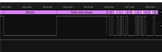
I want to dynamically switch UART TX pin to simulate DMX frames. Specifically, I need the Tx Pin first as a GPIO that can pull up/down Pin level to simulate BREAK/MAB, and then as a UART TX Pin to transmit 512 slot data.

I see someone doing the same thing as me:
https://e2e.ti.com/support/microcontrollers/msp-low-power-microcontrollers-group/msp430/f/msp-low-power-microcontroller-forum/992945/msp432e401y-change-uart-idle-state/3670821?tisearch=e2e-sitesearch&keymatch=DMX#3670821

It doesn't seem to work out well either.

Here's my function:

static void DMX_TX(uint8_t *data, uint16_t len)
{
    UART2_close(uart);
    //IO function change
    GPIO_setConfig(3, GPIO_CFG_OUT_STD | GPIO_CFG_OUT_LOW);
    //BREAK Frame
	GPIO_write(3, CONFIG_GPIO_LED_OFF);
	usleep(88);
    //MAB Frame
	GPIO_write(3, CONFIG_GPIO_LED_ON);
	usleep(8);

   //IO function chang
   /* Access UART */
   uart = UART2_open(CONFIG_UART2_0, &uartParams);

    UART2_write(uart, data, len, NULL);
}

Since I already initialized DIO3 as the UART TX pin when I powered on, I should have disabled UART first in the function, but I didn't find any disable or uninit functions.So I used the close function, but so far the TX Pin has been kept high, which doesn't seem to be working.

I would like to confirm whether such a switch is feasible, and if so, how should I do it?

  • You should not have to open and close the driver (I think). I took the uartExco example from the SDK, and added the following to toggle the TX pin a couple of times for each iteration, and that worked:

        while (1)
        {
            bytesRead = 0;
            while (bytesRead == 0)
            {
                status = UART2_read(uart, &input, 1, &bytesRead);
    
                if (status != UART2_STATUS_SUCCESS)
                {
                    /* UART2_read() failed */
                    while (1) {}
                }
            }
    
            bytesWritten = 0;
            while (bytesWritten == 0)
            {
                status = UART2_write(uart, &input, 1, &bytesWritten);
    
                if (status != UART2_STATUS_SUCCESS)
                {
                    /* UART2_write() failed */
                    while (1) {}
                }
            }
    
            GPIO_setConfigAndMux(CONFIG_GPIO_UART2_0_TX, GPIO_CFG_OUT_STD, IOC_PORT_GPIO);
    
            GPIO_write(CONFIG_GPIO_UART2_0_TX, 0);
            GPIO_write(CONFIG_GPIO_UART2_0_TX, 1);
            GPIO_write(CONFIG_GPIO_UART2_0_TX, 0);
            GPIO_write(CONFIG_GPIO_UART2_0_TX, 1);
            
            GPIO_setConfigAndMux(CONFIG_GPIO_UART2_0_TX, GPIO_CFG_OUT_STD, IOC_PORT_MCU_UART0_TX);
        }

    Siri

  • Hi Siri,

    GPIO_setConfigAndMux is effective for switching pins, thanks for your help. I have one more question about the us delay function,:

    I found that the usleep() function is not accurate, after reading the other problems on the forum, I used the recommended ClockP_usleep() function, it seems to be not accurate either, is there any other solution

    I set a 10-microsecond delay:

    static void DMX_TX(uint8_t *data, uint16_t len)
    {
        GPIO_setConfigAndMux(CONFIG_PIN_UART_TX, GPIO_CFG_OUT_STD, IOC_PORT_GPIO);
    
        //IO function change
        GPIO_setConfig(CONFIG_PIN_UART_TX, GPIO_CFG_OUT_STD | GPIO_CFG_OUT_LOW);
        //BREAK Frame
    	GPIO_write(CONFIG_PIN_UART_TX, CONFIG_GPIO_LED_OFF);
    	ClockP_usleep(10);
        //MAB Frame
    	GPIO_write(CONFIG_PIN_UART_TX, CONFIG_GPIO_LED_ON);
    	ClockP_usleep(10);
    
    	GPIO_setConfigAndMux(CONFIG_PIN_UART_TX, GPIO_CFG_OUT_STD, IOC_PORT_MCU_UART0_TX);
       //IO function chang
       /* Access UART */
        UART2_write(uart, data, len, NULL);
    }

    The actual capture:

    There seems to be a change only when the delay exceeds 1ms, as stated in this link: https://e2e.ti.com/support/wireless-connectivity/bluetooth-group/bluetooth/f/bluetooth-forum/1389192/cc2340r5-short-pause-with-usleep-function-1millisecond/5312278?tisearch=e2e-sitesearch&keymatch=ClockP_usleep#5312278

  • Have you seen the following poast?

    (+) CC1352R: TIRTOS usleep precision - Sub-1 GHz forum - Sub-1 GHz - TI E2E support forums

    You can try to use the CPUdelay function:

    //*****************************************************************************
    //
    //! \brief Provide a small non-zero delay using a simple loop counter.
    //!
    //! This function provides means for generating a constant length delay. It
    //! is written in assembly to keep the delay consistent across tool chains,
    //! avoiding the need to tune the delay based on the tool chain in use.
    //!
    //! \note It is not recommended using this function for long delays.
    //!
    //! Notice that interrupts can affect the delay if not manually disabled in advance.
    //!
    //! The delay depends on where code resides and the path for code fetching:
    //! - Code in flash, cache enabled, prefetch enabled  : 4 cycles per loop (Default)
    //! - Code in flash, cache enabled, prefetch disabled : 5 cycles per loop
    //! - Code in flash, cache disabled                   : 7 cycles per loop
    //! - Code in SRAM                                    : 6 cycles per loop
    //! - Code in GPRAM                                   : 3 cycles per loop
    //!
    //! \note If using an RTOS, consider using RTOS provided delay functions because
    //! these will not block task scheduling and will potentially save power.
    //!
    //! Calculate delay count based on the wanted delay in microseconds (us):
    //! - ui32Count = [delay in us] * [CPU clock in MHz] / [cycles per loop]
    //!
    //! Example: 250 us delay with code in flash and with cache and prefetch enabled:
    //! - ui32Count = 250 * 48 / 4 = 3000
    //!
    //! \param ui32Count is the number of delay loop iterations to perform. Number must be greater than zero.
    //!
    //! \return None
    //
    //*****************************************************************************
    extern void CPUdelay(uint32_t ui32Count);

    Also note that the GPIO_write function take a finite time to execute, so you woul need to compensate for this.

    BR

    Siri

  • Thanks for your answer, this function works very well