This thread has been locked.

If you have a related question, please click the "Ask a related question" button in the top right corner. The newly created question will be automatically linked to this question.

TIDA-010210: Reference Design About;

Part Number: TIDA-010210
Other Parts Discussed in Thread: TIDA-01606

Tool/software:

Hello ,

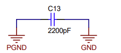
When I examined the reference design, I noticed that there is a capacitor between PGND and GND, there is no other connection, it can provide a reference for reading mains voltages( so AC Voltage), but I think there is a mistake in this design regarding DC bus voltage reading. Neut-PGND is directly short-circuited, by the way.

What do you think about this issue? It does not seem right for the capacitor used to take a reference between two potentials when reading DC voltage.

Best Regards.

  • Hi

    just for your information the voltage measurements in the board are working fine but i agree with you that it looks confusing.

    In general, if you would like to take an example that has less confusion you can use the TIDA-01606 motherboard schematic.

    In this case all the voltage measurements are refered to the middle point.

    Thanks

    BR

    Riccardo

  • Hello Riccardo,

    Actually I understand ,

    Thanks to the AC system in the system, a potential is created between the Y capacitor and the two GNDs. The DC system indirectly gains a reference thanks to this AC system. It's actually a great design :)

    If there was no AC in the measurements then there would be no reference between PGND and GND.

    Best Regards.