This thread has been locked.

If you have a related question, please click the "Ask a related question" button in the top right corner. The newly created question will be automatically linked to this question.

TIDA-010232: HV Isolation Monitoring for 96V BMS

Part Number: TIDA-010232
Other Parts Discussed in Thread: AMC3330, OPA387

Tool/software:

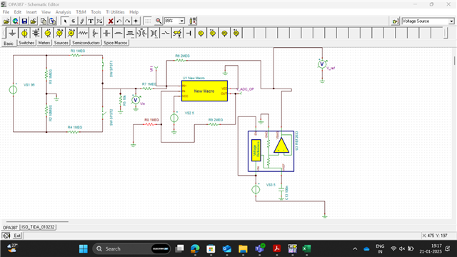
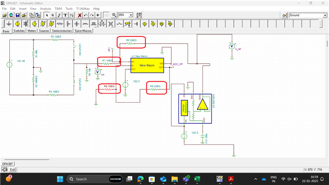
After reviewing the TIDA-010232 we have found it uses AMC3330 as differential amplifier which has two isolated ground reference to its IC. I think design assumes that chassis ground and Microcontroller ground are isolated. But for our 96V BMS design chassis ground and microcontroller ground are same. Can we connect same ground reference to both sides of AMC3330 taking same design reference?

Or there any other good solution which considers the same ground reference for chassis and microcontroller ?

  • Hi,

    Thanks for reaching out.
    Yes in our design we assumed MCU ground and PE/chassis to be isolated from each other.

    You could use the same ground reference for both sides of the AMC3330, but in that case it does not really make sense to use a isolated amplifier.

    Best regards,
    Andreas

  • Hi Andreas,
    Can you suggest any non-isolated amplifier for this application.

  • Hi Nishant,

    I would recommend a precision amplifier here, since offset and gain errors will impact the accuracy.
    For example OPA387 would work well.

    Best regards,
    Andreas


  • Hi Andreas, I have simulated the circuit using OPA387. I have few doubts:
    1. When I am using feedback resistors in kohms range the calculations based on TIDA - 010232 are not matching.
    2. But when I am using the feedback resistors in Megaohms range the calculations based on TIDA -010232 are matching (although I have not checked with many iterations)
    3. This was not the case with AMC3330.

    Can you give your feedback on this. Should I select the feedback resistors in Mohms while using OPA387?
    If possible, can you also give the reason why is this case not happening while using AMC3330, but it happens when using OPA387.

    Thanks, and Regards
    Nishant
     

  • Hi Nishant,

    We never implemented a non isolated system, so I am not 100% sure about the issues.
    I think, the problem with the lower value feedback resistance is, that R7 and R6 are in parallel to R5. So they impact the measured voltage. The feedback resistors should be selected much higher then the measurement resistor, so they do not impact the measurement. 

    Best regards,

    Andreas

  • Thanks for your prompt response.
    Please suggest should we go with the design (OPA387).
    High value feedback resistors (10MEGA to 20MEGA range) will not impact the working of OPA387?
    Then we can go with the design.
    Thanks, and Regards
    Nishant

  • Hi Andreas.
    Thanks for your prompt response.

    Please suggest should we go with the design (OPA387).
    High value feedback resistors (10MEGA to 20MEGA range) will not impact the working of OPA387, like bias current requirement or any other issues?
    Then we can go with the design.
    Thanks, and Regards
    Nishant

  • Hi Nishant,

    It is correct that Bias currents will have a bigger impact for these high feedback resistor values.
    I think you need to find a trade off here. 10MEG to 20MEG might be a bit to high.
    What is the threshold for insulation resistance  in your system. We might also be able to reduce the resistance values of  the voltage divider a bit, which will also help.

    Best regards,

    Andreas

  • Hi Andreas,
    We are designing this HV Isolation monitoring circuit for 96V BMS. And threshold for warning should be 500V/ohm and for fault 100V/ohm. I have simulated the circuit using feedback resistors as 1Mega ohms and 2 Megaohms. The results are close to as per expectations (still little deviations)


    Can these values impact the bias currents? 
    Yes, please you can suggest the resistance values of voltage divider.
    Overall, you can suggest the values of resistances for this whole circuit, or any changes which I should make.

    Thanks, and Regards
    Nishant Kumar

  • Hi Nahant,

    In our tests and simulations we found that accuracy is best if the resistor divider resistance is in the same range as the measured insulation resistance.
    Accuracy is most important at the threshold value, so we selected in the resistance of the voltage divider close to the threshold value. In your case this would be 96V * 500Ohms/V = 48kOhm. 
    So I would suggest to select R3 and R4 in your simulation to 50 kohms and R5 to 500 Ohms. 
    In that case feedback resistors with 100k and 200k could work.

    You still need to simulate this a bit. Since these are just suggestions based on my experience.

    Best regards,

    Andreas