Other Parts Discussed in Thread: PMP31179, UCC28064A
Tool/software:
Hi,
Had anyone done simulation on this reference design? If so, would you share the files and results? If not, any suggestions for simulator, library, etc.?
Regards,
Michael Young
This thread has been locked.
If you have a related question, please click the "Ask a related question" button in the top right corner. The newly created question will be automatically linked to this question.
There is only high level simulation on bridgeless PFC based on Simplis to evaluate the power stage. Not matching exactly UCC2805x behavior.
Hi Sheng-yang,
Just noticed you were the engineer for PMP9640. Looks like I stumbled across the right person.
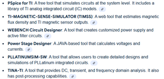
I was hoping that one of the TI's tools out of this list would work. Any thoughts? Using a 3rd party simulator may not be as accurate.

I am working on a power supply design for aerospace applications. It must meet DO-160 specification,115Vac input, 400Hz and a variable range including 400 Hz, 28VDC output. Plus, we need to prepare for component substitutions now and in the future, since 9640 is already 10 years old. As you can see, I really to setup the simulation early on in the design process.
I glanced through the test report and all the information were measurements, sort of after-facts. I need to predict the results before I build an engineering prototype.
Many thanks for your support.
Michael Young
Michael, sorry for my late reply. And sorry we didn't create simulation model based of the simulation tools you listed. But my understanding is CRM operation isn't good for avionic line frequency (e.g. 400Hz). It is very difficult for a CRM PFC like PMP9640 to meet DO-160 harmonic standard.
Hi Sheng-yang,
Yes my design will meet DO-160 A(WF) standard, meaning that it must operate for at least 30 minutes at 800Hz. So, is it just the component issue? In other words, if we choose components that work in 800Hz, can we make PMP9640 compliant for A(WF)?
For Harmonic standard, I am not sure which part you were referring to, Total Harmonic Distortion? Individual Harmonic Content? Harmonic Emissions? To me, they all seem to be component related.
As for simulation, does TI provide spice models for all major components in the PMP9640 design?
Thanks,
Michael
Michael,
I am referring individual harmonic content of input current. My concern is more on control challenges over the components at 800Hz.
I have a Simplis simulation model I created for CRM semi-bridgeless PFC for 60Hz operation. For sure the result is ideal, it won't be as perfect in real case and not matching exactly UCC2805x behavior.
Feel free to change the model to adapt 800Hz line frequency.
https://e2e.ti.com/cfs-file/__key/communityserver-discussions-components-files/234/Bridgeless-PFC.sxsch
There is a reference design using interleaved CRM PFC controller UCC2806x below:
Hi Sheng-yang,
PMP31179 is designed to meet avionics applications, perfect for me! This is a relatively new design (in 2022), so presumably fewer component obsolescence issues. I will use PMP31179 instead of PMP9640, find a 28V transformer for T1, and I am mostly done. Thank you for bring this to my attention.
Now a few follow ups,
1. Could you give me a quick explanation on Q8/Q9/Q10 inrush circuit? I don't follow exactly when Q10 is turned on.
2. How is R65 sensing anything? There is no current. On one end is SGND, the other end it references to SGND.
3. Can I buy this board for evaluation?
4. Would TI sell this board as a product?
5. From the test report, this design meets DO-160G on harmonic limits. Had TI certified this design for compliance?
6. Any simulation done on this design?
Thank you very much!
Michael Young
Hi Michael,
1. Q10 is, of course, shorting the inrush protection RT1 so that it is used only for few milliseconds. Q8 and Q9 ar providing a timer + blanking time to avoid false turn on of Q10. So, when 12V comes (out of RVCC from the LLC controller), C64 activate Q9 and therefore Q8. C64 is there to avoid turn on-off-on during short absence of aux_15V. I admit it's a bit complex circuit, so you may want to replace it with a simple timer, like the one in PMP9640.
2. R65: the ground output of this power supply is actually the net "R_SENSE" and not SGND. That means, the output current flows between R_SENSE and SGND nets, therefore through R65.
3. This board is unfortunately not purchasable, but you can contact your local representation from TI and request to get this board.
4. See point 3
5. We just create custom designs and boards, but we don't do certifications; that typically deferred to our customers
6. I didn't do simulation on this board. I believe your request is concerning simulating the PFC stage, isn't it? In this regard we have a Simplis model on TI.com, available at the link:
https://www.ti.com/lit/zip/slum658
Best regards,
Roberto
Hi Roberto,
Thank you very much.
1. Just to make sure, the "simple timer" you referred to in PMP9640 is R10/C11, right?
2. R65. This is tricky. So does this design have an output connector "J??"? How do you connect to the output?
6. For simulation, PFC is the main concern. But if we also have simulation for other parts and whole board, that would be great.
Regards,
Michael
Hi Michael,
1. The time constant is defined by R4+R5 and R10 (voltage divider) together with C11.
2. Actually the board does not have a real connector Jxx, but the two nets "30V" and "R_SENSE" are simply routed to two pads.
6. Unfortunately we have only simulation file for the PFC controller UCC28064A, but not for the LLC stage (UCC25660x) or whole converter either...
Regards,
Roberto